











Description
-
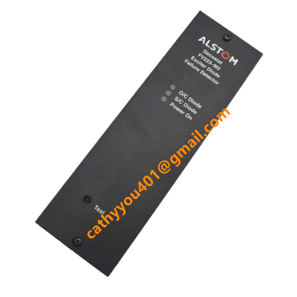
BrandALSTOM
-
ModelFV223-M2
-
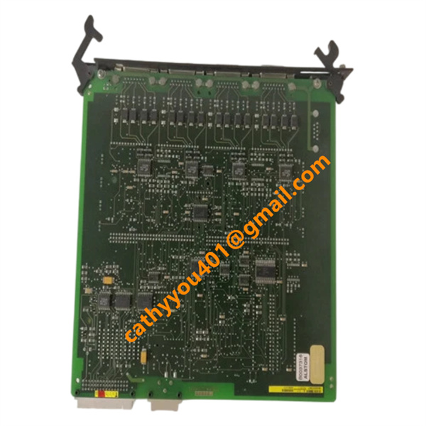
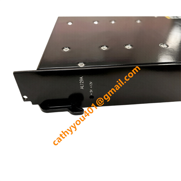
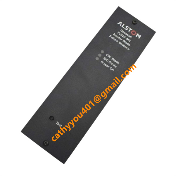
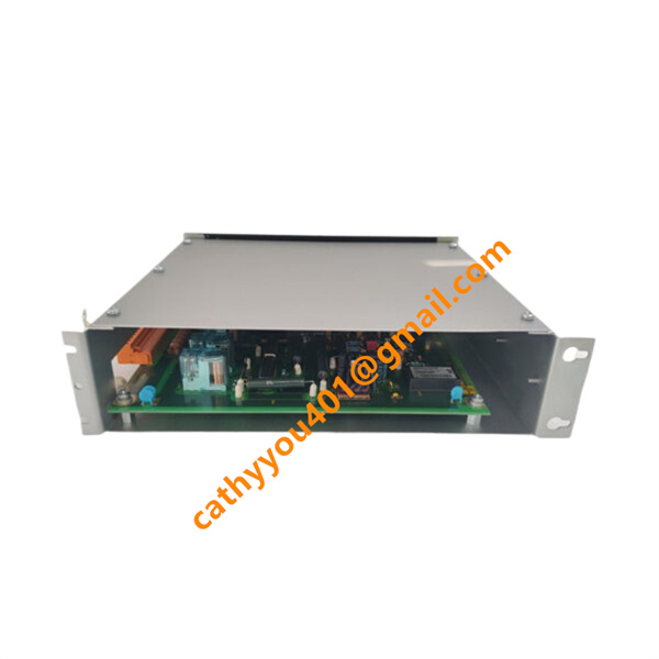
Product NameExcitation Fault Protection Card
-
Country of OriginUnited Kingdom (UK) / France
-
HS Code8538909100
-
Dimensions180 mm x 50 mm x 240 mm
-
Weight2.0 kg
-
Operating Temperature-10 °C to +60 °C
-
Storage Temperature-40 °C to +75 °C
-
Power Supply24vdc
-
Warranty12 month
-
Product StatusNew and original
ALSTOM FV223-M2 Technical Specifications and General Information
Cooling Method: Natural convection inside rack sub-assemblies. Adequate vertical spacing or rack-fan ventilation must be provided if mounted adjacent to high-dissipation excitation elements.
Input Specifications
Auxiliary Control Voltage (Power Supply Input): Typically DC 24 V (Acceptable window of 18 V to 32 V) or AC 110V/220V depending on factory chassis configuration options.
Sensing Signal Input: High-impedance measuring inputs connected via transformers or telemetry to monitor the AC/DC waveforms generated by the brushless exciter.
Local Test Command Input: Dedicated front-panel terminal or push-to-test hardware loop to simulate diode fault signals for circuit verification.
Output and Diagnostic Specifications
Fault Detection Relay Outputs: Equipped with potential-free (dry) contact relays (Normally Open / Normally Closed configurations) rated up to AC 250V / 2A for immediate triggering of a system alarm or hard-wired turbine trip sequence.
Visual Status Indicators (LEDs):
Green LED: Power On / Healthy System Status
Yellow/Amber LED: Warning / Minor Ripple Anomaly / Single Diode Open Circuit
Red LED: Trip State / Exciter Diode Short Circuit / Critical Fault Detected

ALSTOM FV223-M2 Comprehensive Wiring and Installation Steps
Handling, replacing, or wiring excitation protection modules must only be executed when the generator or motor is completely stationary, de-energized, and isolated from both the main grid and the auxiliary field supplies.
Chassis Inspection and Power Off: Shut down the auxiliary power supply feed feeding the GECOSTAT panel or rack sub-assembly. Ensure there is no residual energy on the telemetry inputs.
Slot Selection and PIN Alignment: Slide the FV223-M2 module into its designated rack slot position. Gently guide the module along the chassis rails until the heavy multi-pin rear connectors sit perfectly parallel against the mating backplane socket.
Mechanical Lock-In: Firmly press the faceplate until the module is fully seated. Tighten any integrated thumb screws or locking mechanisms on the front faceplate to ensure continuous ground contact with the chassis frame and to protect against mechanical machinery vibrations.
Sensing Input Wiring: Terminate the sensing signal wires coming from the auxiliary measuring transformers (or the non-rotating pickup loops) to the dedicated input terminal pins on the backplane connector block. Always utilize high-quality, twisted-shielded instrumentation cable to prevent stray EMI from creating false trip conditions.
Relay Output & Trip Circuitry Hookup: Connect the dry alarm/trip relay contacts to the centralized generator protection scheme (such as the master trip relay or DCS monitoring card). Ensure that the contact ratings are not exceeded; use intermediate interposing relays if switching high-current inductive trip coils.
Shield Grounding: Connect the braided cable shields of all incoming telemetry and signal lines to a singular, low-impedance ground point inside the cubicle. Do not ground both ends of the shield to eliminate ground loop currents.
Power-On Test Sequence: Apply auxiliary control power to the rack. Confirm the green "Healthy/Power" LED lights up. Utilize the integrated test/simulation function on the front panel to force a test loop, verifying that the diagnostic indicators change states and the downstream alarm relay trips as expected before clearing the system for machinery startup.

ALSTOM FV223-M2 Key Product Advantages
High-Speed Fault Isolation: Prevents cascading destruction of the rotating rectifier assembly by isolating a single failed diode before it evolves into an expensive multi-diode short circuit.
Solar-Independent Waveform Analysis: Uses advanced harmonic filtering to detect failures electronically via the control lines, avoiding the need for optical sensors that can fail due to carbon dust or grease buildup inside the generator housing.
Rugged Heavy Industrial Build: Engineered under strict aerospace and power utility-grade standards to sustain high vibration and electromagnetic interference (EMI) typical of heavy machine halls.
Clear Front-Panel Diagnostics: Provides field technicians with immediate status indication, simplifying localized trouble-shooting without the immediate need for external software oscilloscopes.



.jpg)