












Description
-
BrandGE
-
ModelIS200BAPAH1A
-
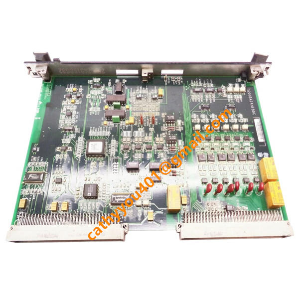
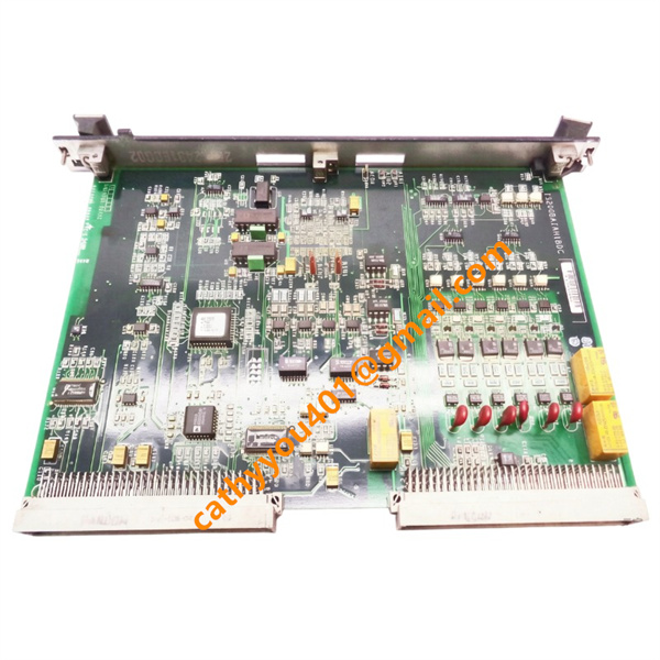
Product NameMark VI System BAPA Passive VME Bus Backplane Assembly Board
-
Country of OriginUnited States
-
HS Code85340090
-
Dimensions233mm H×360mm W×25mm L
-
Weight2.1kg
-
Operating Temperature0°C ~ +60°C
-
Storage Temperature-40°C ~ +85°C
-
Power Supply24vdc
-
Warranty12 month
-
Product StatusNew and original
GE IS200BAPAH1A Passive Backplane Assembly
Electrical Parameters: Voltage & CurrentNominal Input Power Supply: 28VDC ±10% DC power input from EPSM power supply module
Total Maximum Load Current of Whole Backplane: 45A
Single Slot Maximum Output Current: 4A
Built-in Independent Fuse Protection for Each Power Bus
Bus Standard: VME64 industrial bus specification
Interface Connector: DIN 41612 standard 96-pin P1/P2 card edge connectors, A/B/C three-row pin layout
PCB Structure: 6-layer multilayer board, separated power layer, ground layer and signal layer for strong anti-interference performance
10. Slot Configuration: Equipped with 12 standard VME card slots; Slot 1–2 for main controller UCVE/VCMI, Slot 3–12 for DSPX calculation board, SIOB signal board, TRLY relay board and other I/O modules

GE IS200BAPAH1A Core Product Advantages
1. TMR triple modular redundancy compatible design: Three independent backplanes are configured for R/S/T three control cores respectively, realizing physical electrical isolation; single backplane fault will not cause overall system shutdown, greatly improving unit safety and availability.
2. Impedance-controlled PCB wiring layout ensures stable VME bus signal transmission, extremely low signal delay deviation, meets high real-time requirement of turbine emergency trip protection logic.
3. Independent overcurrent fuse protection design for each power output channel, effectively preventing short-circuit damage spreading across the whole backplane.
4. Conformal coating whole-board protection adapts to high temperature, humidity, dust and vibration environment inside power plant control cabinets, extending service life greatly.
5. Passive backplane structure without electronic operation chips, ultra-low failure rate, MTBF reaches 200,000 hours, low later maintenance cost.
6. Standard VME mechanical structure, unified card insertion specification, supports hot swap maintenance of peripheral I/O boards under system online running status.
7. Reserved voltage test points and signal detection terminals on PCB surface, convenient for on-site electrical debugging and fault troubleshooting.

GE IS200BAPAH1A Detailed Wiring Method
1. Main Power Input Wiring
The backplane is reserved with heavy-duty high-current terminal lugs for 28VDC power access from EPSM power supply module.
Positive pole (+): Connect 28VDC output positive wire of system power supply; Negative pole (-): Access DC power negative busbar of control cabinet.
PE protective earth terminal must be firmly connected to cabinet equipotential grounding copper bar to satisfy EMC anti-electromagnetic interference standard, restrain power frequency interference and surge impact.
Recommended wire specification: 6–10AWG high-temperature resistant shielded cable for main power circuit.
2. VME Bus Card Slot Signal & Power Wiring
All power distribution and bus signal transmission adopt internal PCB copper foil wiring without external wiring; operators only need vertical insertion of each functional module into corresponding DIN 41612 96-pin slot:
Main controller card inserted into Slot 1 & Slot 2 for system master control signal interaction
Analog signal acquisition boards, digital input/output boards inserted into middle slots
Relay output and protection interlock boards installed at rear slots
3. External Signal Expansion Terminal Wiring
Several reserved auxiliary terminal blocks on board are used for external auxiliary signal access:
Alarm indication signal terminals: Connect cabinet door fault indicator light, audible alarm device
Auxiliary monitoring test terminals: External multimeter or signal detector for bus voltage and waveform measurement




.jpg)