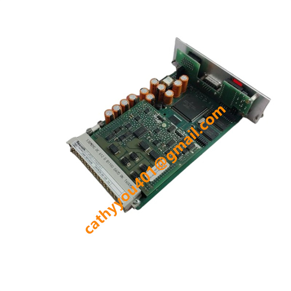





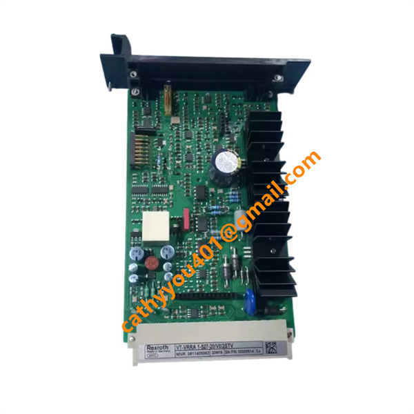
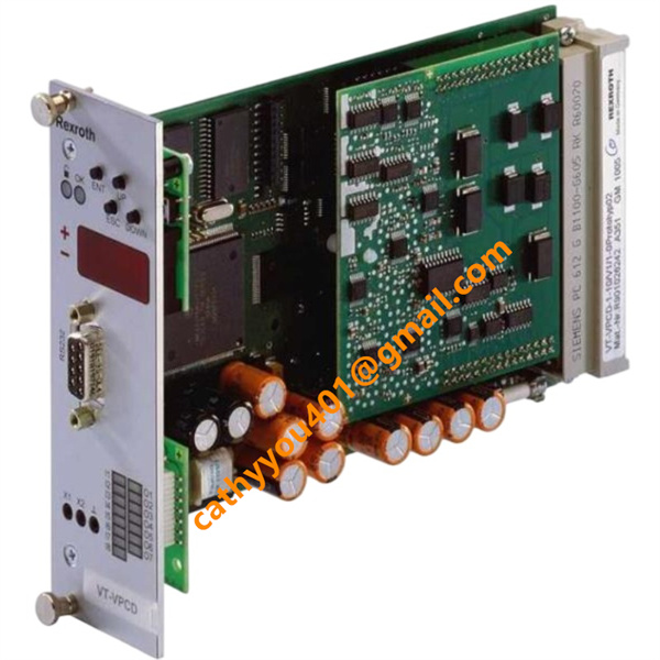







Description
-
BrandBosch Rexroth
-
ModelVT-VPCD-1-1X/V0/1-P-1
-
Product NameDigital Closed-Loop Control Electronics
-
Country of OriginCzech Republic
-
HS Code85437090
-
Dimensions160mm×100mm
-
Weight0.2 kg
-
Operating Temperature0 ℃ ~ +50 ℃
-
Storage Temperature-40 ℃ ~ +85 ℃
-
Part NumberR901089559
-
Warranty12 month
-
Product StatusNew and original
Bosch Rexroth R901089559 VT-VPCD-1-1X/V0/1-P-1 Product Introduction & Technical Specifications
Electrical Parameters
Rated Supply Voltage: 24 VDC; operating range 21 VDC ~ 30 VDC (-10% / +40% tolerance)
Max Total Current Consumption: 3.5 A @ full load
Main Control Scan Cycle: 2 ms deterministic loop
Analog Setpoint Input Signals: ±10 VDC, 0–10 VDC, 0–20 mA, 4–20 mA
Pump Solenoid Drive Output: Clock current regulation, output range 0–3 A, load impedance 2–45 Ω
Feedback Signal Acquisition: Inductive swivel angle sensor signal, 5 kHz oscillator frequency
Communication Interfaces1. RS232 D-Sub 9pin front port: BODAC software parameterization & debugging
Relative Humidity: 5%–95% non-condensing
Max Operating Altitude: ≤ 2000 m without performance derating
Vibration Resistance: Complies with IEC 60068-2-6 industrial cabinet standard
EMC Compliance: EN 61000-6-2 heavy industrial anti-interference standard

R901089559 VT-VPCD-1-1X/V0/1-P-1 Bosch Rexroth Core Product Advantages
1. All-In-One Multi-Loop Control: Integrates swivel angle, pressure and power closed-loop control in single card, eliminates extra signal conditioning modules and saves cabinet space.
2. Digital Precision Parameterization: All ramp time, gain, bias and power limit values can be digitally set via front panel or BODAC software, high repeatability without mechanical potentiometer drift.
3. Master-Slave Synchronization & Mooring Function: Supports multi-pump master-slave linkage and static pressure mooring holding for stable pressure output under standby status.
4. Built-In Leakage Compensation Algorithm: Automatically compensates hydraulic system internal leakage to maintain constant system pressure under variable load conditions.
5. Dual Diagnosis Channels: Front test sockets + LCD fault code display; real-time alarm for sensor wire break, short circuit and drive circuit failure for rapid maintenance.
6. Rich Industrial Bus Compatibility: PROFIBUS DPV0 + RS232 dual communication, seamless data exchange with mainstream PLC, DCS and upper monitoring systems.
7. Expandable Local Bus Network: Up to 32 VT-VPCD cards connected on one local bus to realize large multi-pump hydraulic station centralized control.
8. Rugged Industrial PCB Design: Reinforced anti-vibration circuit layout, wide temperature operating range, low failure rate for long-term continuous heavy-duty operation.

R901089559 VT-VPCD-1-1X/V0/1-P-1 Bosch Rexroth Standard Wiring Method
Step 1 24 VDC Power Supply Wiring
Connect cabinet 21–30 VDC control power to the designated power pins of the rear 64-pin DIN connector; strictly distinguish positive and negative polarity. Install independent fast fuse at power inlet for short-circuit protection; single-end ground power cable shielding to cabinet protective earth bar.
Step 2 Analog Setpoint Signal Wiring
Use shielded twisted pair cables to connect PLC analog output or external command potentiometer to analog input terminals. Separate low-level signal wires from high-power AC cables with minimum 20 cm clearance to avoid electromagnetic interference; ground shielding only at cabinet earth bar.
Step 3 Pump Feedback Sensor Wiring
Route shielded cables from pump swivel angle inductive sensor and system pressure transducers to feedback signal pins; control single cable length within 300 m to guarantee closed-loop control precision.
Step 4 Proportional Solenoid Drive Wiring
Connect pump HS4/EO4 proportional solenoid coils to PWM current output terminals; match coil impedance within 2–45 Ω range as per pump specification.
Step 5 Communication Bus Wiring
1. RS232 Debug Port: Connect 9pin serial cable to PC for BODAC software parameter download and fault data reading.
2. PROFIBUS DPV0: Double-shielded twisted pair for bus A/B lines, install 120Ω matching resistor at the last card of the bus trunk.
3. Local Bus Cascading: Special bus cable for multi-card master-slave networking, follow maximum 280 m length limit.
Step 6 Protective Grounding & Pre-Power-On Inspection
1. Connect the metal front panel ground terminal and all signal cable shielding layers to cabinet common protective earth busbar to eliminate ground loop interference.
2. Check all rear connector pins for full insertion, tighten terminal wiring without loose contact or short circuit between channels.
3. Complete offline signal simulation test to verify pressure, swivel angle closed-loop regulation and fault diagnosis functions before pump commissioning.
4. After power-on, set pump control parameters via front panel or BODAC software, confirm LCD real-time data display and bus communication data upload operate normally.


.jpg)