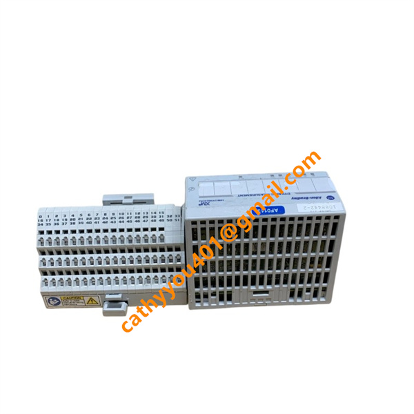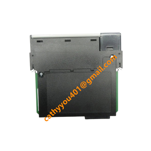





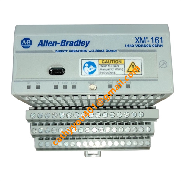
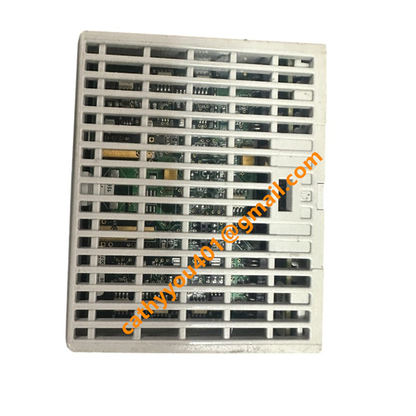







Description
-
BrandAllen-Bradley
-
ModelXM-161 1440-VDRS06-06RH
-
Product Name
-
Country of OriginUnited States
-
HS Code8543709900
-
Dimensions97mm×94mm×94mm
-
Weight97mm×94mm×94mm
-
Operating Temperature-20°C ~ +65°C (-4°F ~ 149°F)
-
Storage Temperature-40°C ~ +85°C (-40°F ~ 185°F)
-
Power Supply24VDC
-
Warranty12 month
-
Product StatusNew and original
Allen-Bradley XM-161 1440-VDRS06-06RH Technical Specification
Electrical Parameters
Main Supply Voltage: DC 24V, allowable fluctuation range: 18 VDC ~ 32 VDC, Class 2 / SELV safety circuit standard
Typical Operating Current: 0.31 A @ 24 VDC
Maximum Working Current: 0.40 A @ 18 VDC
Power Consumption: Typical 7.4 W @ 24 VDC; Max 8 W @ 32 VDC
IEPE Sensor Excitation Current: 2.69 mA constant current per channel, tolerance ±20% for powering industrial accelerometers
4–20mA Analog Output Parameters:
Two isolated groups with three outputs each, one output corresponding to one vibration channel; External loop power required: 7~36 VDC; Max load resistance 600 Ω; Measurement accuracy ±0.5% FS maximum, typical ±0.2% FS; Response time 1.5 seconds (3τ)
Overcurrent Protection: Matched external 5A fuse kit (440-5AFUSEKIT) for power circuit protection

XM-161 1440-VDRS06-06RH Detailed Wiring & Connection Instructions
1. Main DC 24V Power Wiring
Power positive terminal No.37 connects +24 VDC, public negative terminal links 0V/GND; all power cables must adopt shielded twisted cables
Shield layer implements single-end earthing inside control cabinet to suppress industrial electromagnetic interference
Total wiring distance between power supply and terminal base shall not exceed 10 meters; longer wiring requires additional EMI filter installation in series on power line
2. Vibration IEPE Accelerometer Sensor Wiring
Six channel field wiring terminals on 1440-TB-H base correspond to Channel 1~Channel 6 input interfaces
Wiring definition: Cable core conductor connects signal positive terminal; shielding braid wire is connected to terminal ground pin; do not ground both cable ends to avoid ground loop noise
Constant current excitation inside module supplies power to accelerometers directly without separate external sensor power supply
3. Isolated 4–20mA Analog Output Wiring
Six analog output terminals are divided into two isolated three-channel groups for anti-interference separation
External 7–36 VDC loop power source needs to be connected into the current loop together with PLC analog input card; positive pole matches output positive terminal, negative pole connects public loop ground
Do not exceed 600Ω total loop load resistance to guarantee linear output precision
4. DeviceNet Communication Bus Wiring
DeviceNet field bus terminals adopt standard industrial shielded bus cable wiring; follow trunk-drop line wiring specification, install terminal resistors at two ends of total bus trunk
Communication baud rate supports auto-switching: 125 kbps, 250 kbps, 500 kbps for different bus transmission distances

XM-161 1440-VDRS06-06RH Core Product Advantages
1. Six Independent Vibration Inputs + Matched Isolated 4–20mA Outputs: Each vibration channel corresponds to one analog signal output, directly interfacing with conventional process control systems, eliminating extra signal conversion hardware.
2. On-board Independent Vibration Calculation & Alarm Logic: Embedded processor executes real-time overall vibration RMS/peak value computation, high/low alarm setup and relay trigger logic without PLC intervention, achieving hardware-level fast equipment protection.
3. Dual Communication Architecture: Supports DeviceNet industrial fieldbus for upper system networking and XMbus backplane bus for multi-XM module cascading, flexible system expansion for multi-machine monitoring racks.
4. Compatible with Standard IEPE Accelerometers: Built-in constant current excitation circuit, plug-and-play for mainstream industrial vibration sensors, adaptable to field existing measuring equipment.