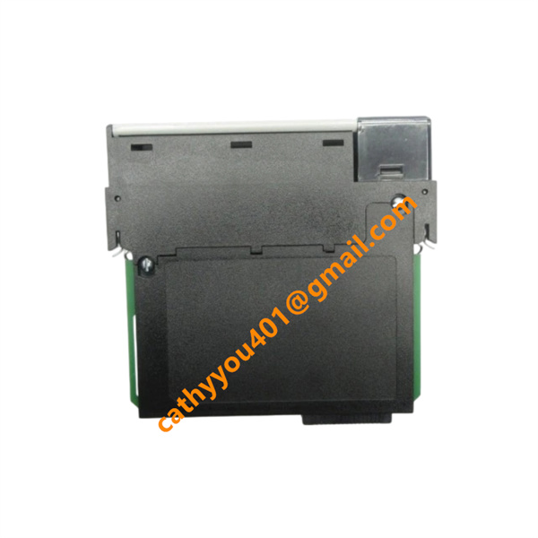





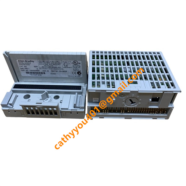
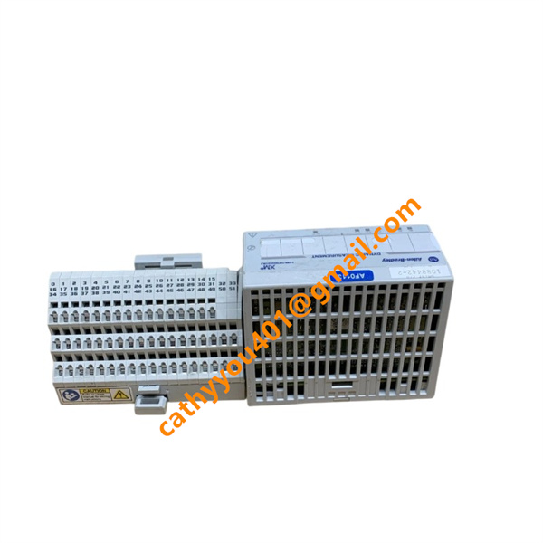







Description
-
BrandAllen-Bradley
-
Model1440-DYN02-01RJ
-
Product Name
-
Country of Origin
-
HS Code
-
Dimensions
-
Weight
-
Operating Temperature
-
Storage Temperature
-
Power Supply24VDC
-
Warranty12 month
-
Product StatusNew and original
Allen-Bradley 1440-DYN02-01RJ Complete Product Specification
Core Technical Parameters
1. Rated Working Voltage: 24 VDC SELV power supply (allowable fluctuation: 18 VDC ~ 30 VDC)
2. Max Operating Current: 0.3 A @ 24 VDC; Maximum total power consumption: 7 W
3. Input Configuration: 2 dynamic measurement channels, 1 tachometer speed channel
4. Signal Output: Buffered analog output per channel, internal logical relay alarm output
5. Communication Bus: XM-Net dedicated internal bus, upper-level ControlNet via 1440-ACNR adapter
6. Protection Class: IP20 (cabinet internal installation only)
7. Relative Humidity: 5% -95% non-condensing
8. Installation Method: Standard DIN rail mounting
9. Isolation Voltage: 250 V continuous basic insulation

Allen-Bradley 1440-DYN02-01RJ Standard Wiring & Connection Method
1. Power Supply Wiring
Positive terminal: Connect stabilized 24 VDC Class 2 industrial control power positive pole;
Negative terminal: Connect power negative pole and cabinet protective ground simultaneously;
Use independent shielded DC cables, separate power wiring from signal wiring to avoid interference.
2. Field Sensor Signal Wiring
Channel 1 & Channel 2 dynamic input terminals: Connect IEPE accelerometers, eddy probes or velocity sensors with shielded twisted-pair cables;
Tachometer input terminal: Connect magnetic pickup or eddy current speed probe for rotational speed collection;
All sensor shielding layers are single-point grounded only at the cabinet end.
3. XM-Net Bus Communication Wiring
Connect the module to the 1440-ACNR ControlNet adapter via dedicated XM bus cable in daisy-chain topology;
Strictly follow the bus address sequence during wiring, do not form closed loops.
4. Buffered Analog Output Wiring
Each channel buffered output terminal connects to 4-20mA monitoring instruments or secondary display equipment;
Wiring Precautions
All wiring operations must be completed under full power-off status of the entire XM system;
High-current power cables and weak sensor signal cables must be routed separately;
After wiring, configure module addresses and sensor parameters via Rockwell RSLogix software before commissioning.

Allen-Bradley 1440-DYN02-01RJ Product Advantages
1. Multi-type sensor compatibility, freely adaptable to vibration, displacement, pressure and strain measurement without hardware replacement;
2. Onboard high-speed signal processing chip, independent calculation of vibration peak, RMS, spectrum and order analysis data, reducing PLC computing load;
3. Flexible multi-level alarm threshold configuration, supporting equipment early warning and fault interlock protection logic;
4. Compact DIN rail structure, high module density, saving cabinet installation space;
5. Stable XM-Net bus architecture, up to 10 DYN02 modules can be connected under one 1440-ACNR adapter, convenient system expansion;
6. Excellent EMC anti-electromagnetic interference design, stable operation in strong vibration and electromagnetic industrial environments;
7. Seamless integration with Rockwell ControlLogix PLC system, native CIP protocol communication without additional gateways;
8. Global Rockwell official technical support and complete long-term spare parts supply chain.