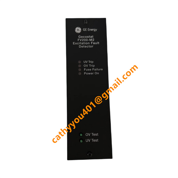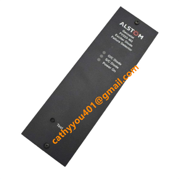





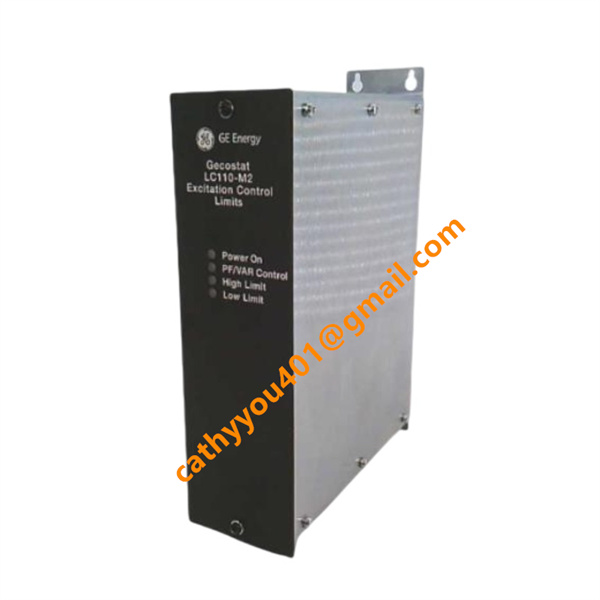







Description
-
BrandALSTOM
-
ModelLC110-M2 REP/K107 52/A1
-
Product NameGECOSTAT Generator Excitation Automatic Regulation Control Module
-
Country of OriginFrance
-
HS Code85389090
-
Dimensions177mm×266mm×210mm
-
Weight1.18 kg
-
Operating Temperature-10 ℃ ~ +60 ℃
-
Storage Temperature-40 ℃ ~ +85 ℃
-
Power Supply24 VDC
-
Warranty12 month
-
Product StatusNew and original
ALSTOM LC110-M2 REP/K107 52/A1 Product Introduction & Technical Specifications
Electrical Parameters
Auxiliary Supply Voltage: Universal dual supply 100–240 VAC / 24–250 VDC
Rated Power Consumption: ≤14 W
Voltage Input (PT Secondary): 100 V AC standard measurement signal, accuracy Class 0.2
Current Input (CT Secondary): 1 A / 5 A selectable, measurement accuracy Class 0.5
Regulation Precision: Terminal voltage steady-state control accuracy ≤ ±0.5% rated voltage
Digital Input Channels: 8 passive dry contact inputs (auto/manual switch, external interlock, test signal)
Relay Output Channels: 5 isolated programmable alarm/trip dry contact outputs
Analog Output: 2 channels 4–20 mA standard signal for remote DCS monitoring of excitation current and voltage
Communication Interface: RS485 Modbus RTU (standard); Profibus DP optional
Operating Current Draw: Max 160 mA under rated auxiliary voltage
Insulation Strength: 2500 V RMS isolation between power loop, signal loop and ground

LC110-M2 REP/K107 52/A1 ALSTOM Core Product Advantages
1. Dual Automatic-Manual Cooperative Control: Perfectly matched with MC15-M2 manual module, seamless auto/manual switching without excitation current fluctuation, no generator reactive power impact during mode switch.
2. High-Stability Voltage Closed-Loop Regulation: Advanced PID+PSS power system stabilizer algorithm, effectively suppress generator low-frequency oscillation and improve grid connection stability.
3. Full-Range Excitation Protection Logic: Built-in overexcitation limiting, underexcitation limiting, V/Hz overflux protection, loss-of-field protection and reverse reactive power protection to avoid generator rotor damage.
4. Local Visual Operation & Debugging: Front-panel LCD display and physical operation buttons support on-site parameter calibration, real-time data monitoring and fault record query without upper computer.
5. Complete Fault Event Storage: Non-volatile memory stores up to 200 time-stamped fault records, convenient for post-trip failure analysis and equipment maintenance.
6. Ultra-Wide Universal Auxiliary Power: Compatible with AC and DC control power supply schemes of all power plant cabinets, no additional isolation transformer required.
7. Strong Cabinet Anti-Interference Performance: Multi-stage isolation circuit and full shielding design, stable operation in high-voltage excitation cabinet with severe electromagnetic interference.
8. Standard Industrial Safety Certification: Comply with IEC 60255 electrical control standard, CE certified, long service life and low failure rate for long-term unattended power plant operation.

LC110-M2 REP/K107 52/A1 ALSTOM Standard Wiring Method
Step 1 Auxiliary Power Supply Wiring
Connect AC/DC auxiliary power cables to dedicated rear power terminals; strictly distinguish DC positive and negative polarity. Install independent fuses at power inlet for short-circuit protection; single-end ground the power cable shielding layer to cabinet protective earth bar.
Step 2 PT Voltage & CT Current Signal Wiring
Run shielded twisted pairs from voltage transformer secondary and current transformer secondary to module measurement terminals. CT secondary loop must keep continuous grounding; CT open circuit is strictly forbidden during operation. Separate weak signal cables from high-power excitation cables to avoid EMI interference.
Step 3 Digital Input Interlock Wiring
Wire external dry contact signals (auto/manual mode switch, unit running status, remote test command) to 8 digital input channels; all inputs adopt passive contact loops without built-in power supply.
Step 4 Alarm & Trip Relay Output Wiring
Connect 5 relay dry contact terminals to cabinet alarm indicator and excitation system trip interlock loop. Relay contacts carry no internal power; independent external control power must be configured for output loops.
Step 5 4–20mA Analog Output Wiring
Connect analog output channels to DCS/PLC analog input modules, adjust external loop resistance per system drawing to guarantee accurate remote signal transmission.
Step 6 RS485 Communication Bus Wiring
Use double-shielded twisted pair for Modbus communication terminals; install terminal matching resistance at the last module of communication bus to eliminate signal reflection distortion.
Step 7 Cabinet Protective Grounding
Connect the module dedicated ground terminal and all signal cable shielding layers to the cabinet common protective earth busbar to eliminate static electricity and common-mode interference.
Step 8 Pre-Power-On Inspection
1. Check all wiring polarity, channel sequence and terminal screw tightness, confirm no short circuit between terminals.
2. Verify CT secondary loop continuous grounding to prevent high-voltage hazard caused by open circuit.
3. Complete offline voltage and current signal simulation test to verify automatic regulation and protection trip functions before unit commissioning.
4. Download excitation parameters via ALSTOM MC-Soft supporting software after power-on, confirm automatic voltage stabilization and remote communication data upload work normally.


.jpg)