





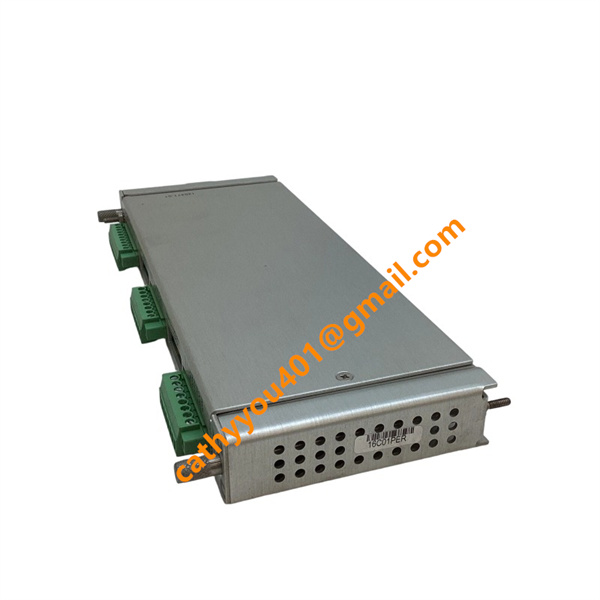
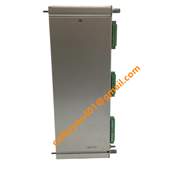







Description
-
BrandBently Nevada
-
Model3500/44-02-01
-
Product NameAeroderivative GT Vibration Monitor
-
Place of OriginUnited States
-
HS Code85389000
-
Dimensions241.3 mm × 24.4 mm × 241.8 mm
-
Weight0.91 kg
-
Operating Temperature-40 °C to +70 °C
-
Storage Temperature-40 °C to +85 °C
-
Power Supply24VDC
-
Warranty12 month
-
Product StatusNew and original
Backed by abundant in-stock inventory and nearly 20 years of industry experience, our company stands as a leading player in the industrial control sector.We offer an extensive range of industrial control products covering numerous models. Should you have any other requirements, please feel free to contact us, and we will respond to you promptly.
Our main brand:
1.ABB's module cards, touch screens, controllers, etc., such as PP846 touch screen, IGCT starting with 5SHY, PM starting controller, AI, DO starting input/output module, SP starting Bailey module, etc
2.GE's module card CPUs, such as VMIC starter, IS200, IS215, IS400, IS420 series, etc,
3.Emerson's card components and EPRO probes, Westinghouse 1C series, Honeywell CC series, Schneider 140 series, Envision full series, Bentley 3500 series, Rexroth motors and drives, and Foxboro small modules.
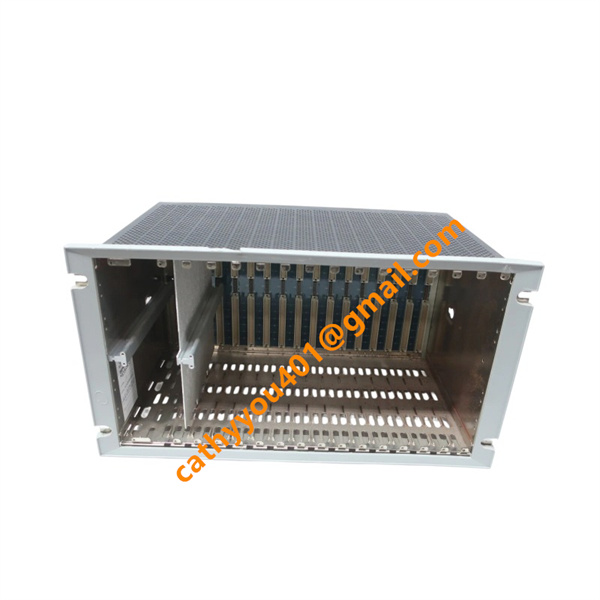
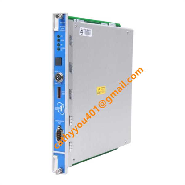
Model: 3500/44M Aeroderivative GT Vibration Monitor (4-channel vibration monitor)
Inputs
4 × Vibration sensor AC inputs (BNC front panel):
Accelerometer / Velomitor / Proximitor sensor signals
2 × Keyphasor speed reference inputs (supports tracking filter per channel pair)
Backplane communication input (3500 rack internal bus)
Outputs
Buffered sensor signal outputs (front panel BNC, waveform monitoring)
4 × Configurable 4–20 mA recorder analog outputs (via rear I/O module)
Alarm logic signals transmitted to rack relay modules (3500/32M / 3500/33)
Digital data output via rack backplane to communication module (3500/22M) for System 1 / DCS
Front panel status LED indicators (OK, Alert, Danger, Channel Fault)
1. Pre-operation Inspection
Ensure the module is fully seated within the 3500 rack and secure the module latches.
Confirm the matching rear Aero GT I/O module is properly installed.
Inspect wiring for vibration sensors, BNC buffered output cables, Keyphasor wiring and 4–20 mA analog output circuits.
Verify the rack power supply is in normal condition and no short-circuit exists on field wiring loops.
Check front panel LED status; the OK indicator shall remain off prior to power energization.
2. Power On and Self-test
Switch on the power supply of the 3500 rack.
Observe the module self-test sequence; the OK LED flashes during startup.
Upon self-test completion: steady OK LED indicates normal status; flashing or red LED denotes module fault.
Check periodic blinking of Tx/Rx communication LED to confirm reliable backplane communication with the rack.
Note: If self-test fails, re-seat the module or replace it with a spare unit.
3. System Configuration via Rack Configuration Software
Connect a PC to the communication port of the 3500 rack.
Start Rack Configuration Software and establish communication with the target rack.
Upload the existing rack configuration or create a new project file.
Select the corresponding module type for the target slot: 3500/44M.
Configure parameters for each vibration channel as below:
Sensor type selection: Accelerometer / Velomitor
Measurement unit, frequency range and filter mode (1X tracking / bandpass / integration)
Assign Keyphasor input for tracking filter function
Set Alert and Danger setpoints together with alarm time delays
Define scale range for 4–20 mA analog outputs
Select multimode alarm group (support up to 8 machine operating modes when necessary)
Download configuration to the rack and wait until downloading completes.
Confirm the module receives configuration without error messages.
4. Signal Commissioning and Verification
Terminate vibration sensors and Keyphasor transducer to field terminals.
Utilize front-panel BNC buffered outputs to monitor raw AC vibration waveforms by oscilloscope.
Compare real-time readings on the 3500 display / System 1 with measurements from portable vibration tester.
Validate Keyphasor signal acquisition and confirm valid calculation of 1X amplitude and phase angle.
Test 4–20 mA analog outputs to ensure output signals match vibration magnitude.
Simulate vibration variation to verify analog outputs respond correctly to measured values.
5. Alarm Function Test
Adjust vibration signal or adopt software force function to exceed the Alert setpoint:
Confirm activation of channel alarm status
Check alarm signals are transmitted to relay modules (3500/32 / 3500/33)
Verify alarm events are recorded in the system event list
Raise the signal above Danger setpoint to test high-level protection alarm.
Test alarm reset and acknowledge functions after measured values return to normal range.
Enable channel bypass function during maintenance and confirm bypass status indication.
6. Normal Operation Monitoring
Monitor real-time vibration amplitude, 1X component and phase angle continuously via HMI or System 1 software.
Track trend curves to identify abnormal vibration escalation.
Carry out regular checks on front panel LEDs:
Steady OK LED: normal operating status
Illuminated Bypass LED: channel inhibited
Fault LED: sensor open/short circuit or module hardware failure
Periodically review event logs for channel faults, configuration modifications and alarm records.
7. Maintenance and Bypass Operation
Activate relevant channel bypass before disconnecting sensors to prevent false alarms or trips.
Avoid hot-swapping the module while machine protection remains active.
Internal circuits of the module cannot be repaired on site; replace with spare unit once hardware fault occurs.
Back up all configuration parameters prior to module replacement for fast recovery.
8. Troubleshooting Guidelines
OK LED off / persistent fault: Check rack power supply, re-seat module and inspect backplane contact of I/O modules.
No vibration measurement readings: Check sensor wiring, transducer integrity and channel configuration.
Abnormal 1X tracking: Verify Keyphasor wiring, pulse amplitude and relevant configuration settings.
Abnormal 4–20 mA outputs: Inspect loop wiring, scale configuration and load resistance.
Communication interruption: Check status of rack interface module (3500/22M) and backplane connection.
9. Power-off Procedure
Cancel channel bypass after maintenance work is completed.
Avoid cutting off rack power when machine protection is activated.
For system shutdown works: Isolate rack power supply only after confirming the machine is under safe status.

Frequently Asked Questions (FAQ)
1.How fast will you reply to my inquiry?
We process all inquiries efficiently and will respond promptly once we receive your message.
2.Do you carry large inventory of industrial control parts?
We maintain massive ready stock of mainstream automation spare parts to shorten lead times.
3.Can you source discontinued or obsolete PLC & DCS modules?
Absolutely.
We specialize in sourcing hard-to-find, obsolete and out-of-production industrial control components.
4.Do you inspect goods before shipment?
Every product undergoes thorough inspection before packing and dispatch.
5.Can you ship orders worldwide?
We provide global shipping with flexible logistics for urgent and regular orders.
6.What payment methods are available?
We accept multiple secure payment options. Please contact our sales team for detailed terms.
7.Do you offer warranty on industrial control spare parts?
Warranty differs by product.
Confirm specific warranty details with us prior to ordering.
8.Are your automation parts new or used?
We supply both new and fully tested used industrial control spare parts.
Please state your needs in your inquiry.
9.What is your typical delivery lead time?
In-stock items can be shipped quickly.
We will advise exact lead time for out-of-stock products after stock verification.
10.Can you offer technical support to check model compatibility?
Yes.Our professional team provides technical support to verify specifications and model compatibility.