











Description
-
BrandGE
-
ModelIS420UCECH1B
-
Product NameUCEC Controller
-
Country of OriginUnited States
-
HS Code85389091
-
Dimensions18.0 cm x 10.0 cm x 5.0 cm (Approx. 7.1" x 3.9" x 2.0")
-
Weight0.50 kg (1.10 lbs)
-
Operating Temperature-30°C up to +65°C (-22°F to +149°F)
-
Storage Temperature-70°C up to +150°C
-
Power Supply24 V DC
-
Warranty12 month
-
Product StatusNew and original
GE IS420UCECH1B Processing Core & Operating Architecture
Processor Engine: High-performance 1.2 GHz AMD G-Series Quad-Core processor equipped with dedicated hardware acceleration.
Operating System Environment: Runs a real-time hypervisor executing the QNX Neutrino multitasking OS, specifically selected for time-critical, high-speed industrial turbine safety loops.
Redundancy Modes: Fully supports the absolute spectrum of Mark VIe configurations:
Simplex: Single controller operation.
Dual Redundancy: Utilizing two ports for cross-domain syncing (S/SL2 and R/SL1 interfaces).
TMR (Triple Modular Redundancy): Harnessing three synchronized controller units simultaneously to guarantee voting logic down to individual application points.
Maintenance Integrity: The combined software and internal memory architecture ensures that if a controller must be shut down or hot-swapped for maintenance, zero individual application inputs are lost to the rest of the operational stack.

Complete Wiring and Port Assignment Guide for IS420UCECH1B
1. Power Supply Wiring
The power interface located at the bottom of the module introduces the 24V primary power source.
Wiring Method: Connect to the power distribution board (such as the JPDG pack) inside the Mark VIe cabinet using a dedicated power cable, which typically features a secure twist-lock or latching plug.
Voltage Requirements: Rated at 24 VDC nominal (with an allowable operational input window typically spanning from 20V to 36V DC).
2. Core Control Layer Network Ports (UCSCH1 Base Ports)
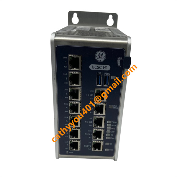
The base layer of the module (the primary controller board section) contains the core Ethernet interfaces utilized for system redundancy and cabinet control network (IONet) communications. These utilize standard 10/100/1000 Base-TX RJ45 ports:
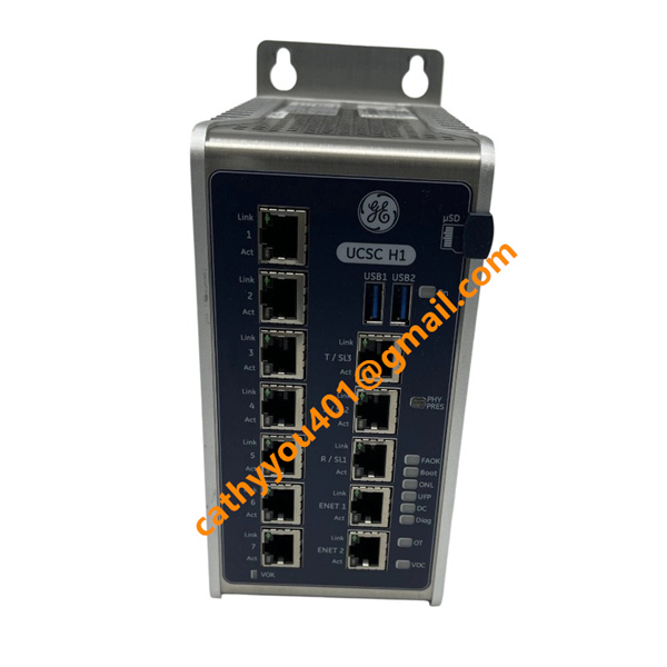
R/SL1 Port: In Dual-redundant or Triple Modular Redundant (TMR) setups, this port connects to the R-Core network switch to handle real-time state synchronization and data voting.
S/SL2 Port: In Dual-redundant or TMR configurations, this port connects directly to the S-Core network switch.
T/P1 Port: In TMR systems, this port routes directly to the T-Core network switch.
Architecture Configuration Note: If the control topology is running in Simplex (Single-channel) mode, only a single IONet switch connection is required. For TMR configurations, all three primary controller ports (R, S, and T) must be fully terminated into their respective independent network domains to drive the hardware-level 2-out-of-3 voting logic.

3. 7-Port RJ45 Ethernet Expansion Board Wiring
The defining visual and functional feature of the IS420UCECH1B variant is the inclusion of 7 additional RJ45 expansion ports located on the front faceplate. These are used to expand down-grid device connections or hook into upper-level networks:
Downstream IONet Topology: Used for the direct, daisy-chained expansion to various remote distributed I/O modules (such as turbine blade speed sensors, thermocouple acquisition packs, and servo valve control blocks). These form real-time deterministic control loops via shielded twisted-pair cables.
Upper-Level Plant Communications & Cloud Bridging:
(1) Connects directly to localized Operator HMI nodes or centralized historian database servers.
(2) Leverages built-in Embedded Field Agent (EFA) technology to establish secure outbound data pipelines to the plant-wide Predix cloud environment or secondary off-grid predictive diagnostics servers.
(3)Protocol Compatibility Matrix: Ensure that all targeted peer devices are configured to communicate using compatible industrial standard layers, such as Modbus TCP/IP, EGD (Ethernet Global Data), or PROFINET.
4. Bottom Interface Allocation
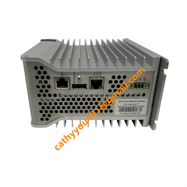
The bottom panel of the module housing retains specialized physical communication and maintenance vectors:
COM Port: An industrial serial communication portal (RS-232/485 diagnostic interface) used to attach a local workstation or field engineer's laptop via a specialized serial debugging adapter cable.
DisplayPort (DP): Used for direct localized video/display output. This port is strictly reserved for factory acceptance testing or extreme low-level kernel recovery procedures in the field.