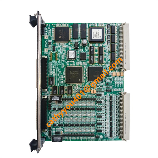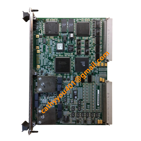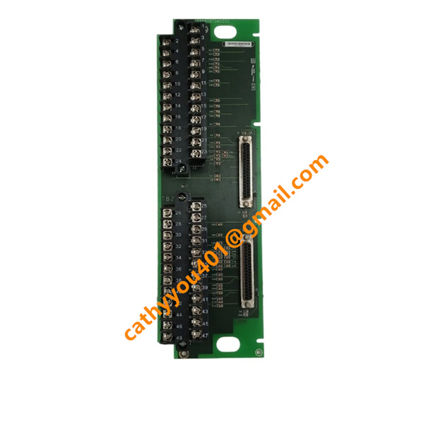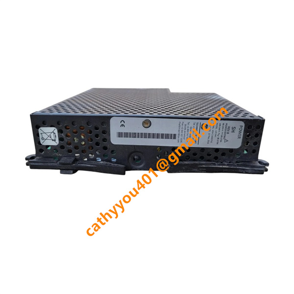






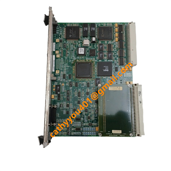
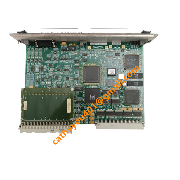







Description
-
BrandGE
-
ModelIS200VTURH2BAC
-
Product NameVibration Transducer Interface / Turbine Protection VME Board
-
Place of OriginUnited States
-
HS Code8537101190
-
Dimensions278 mm × 162 mm × 34 mm
-
Weight0.45 kg
-
Operating Temperature-30 °C to +65 °C
-
Storage Temperature-40 °C to +85 °C
-
Power Supply24VDC
-
Warranty12 month
-
Product StatusNew and original
Backed by abundant in-stock inventory and nearly 20 years of industry experience, our company stands as a leading player in the industrial control sector.We offer an extensive range of industrial control products covering numerous models. Should you have any other requirements, please feel free to contact us, and we will respond to you promptly.
Our main brand:
1.ABB's module cards, touch screens, controllers, etc., such as PP846 touch screen, IGCT starting with 5SHY, PM starting controller, AI, DO starting input/output module, SP starting Bailey module, etc
2.GE's module card CPUs, such as VMIC starter, IS200, IS215, IS400, IS420 series, etc,
3.Emerson's card components and EPRO probes, Westinghouse 1C series, Honeywell CC series, Schneider 140 series, Envision full series, Bentley 3500 series, Rexroth motors and drives, and Foxboro small modules.
1. Backplane Operating Power
Operating Supply Voltage: 12 VDC / 24 VDC (Mark VI VME rack backplane power)
Operating Current: Low-power consumption, typical working current < 200 mA
2. Field Analog Input Specifications
Common Mode Input Voltage Range: ±5 V
Differential Signal Input Range: 0–10 VDC standard industrial vibration/speed signal
Input Type: High-impedance analog input (near-zero input current, no load current consumption)
Isolation Voltage: 1500 V RMS galvanic isolation between field side and control side
3. Sensor Excitation Output
On-board sensor excitation voltage: 24 VDC
Max Excitation Output Current: 100 mA (for powering vibration probes and speed sensors)
4. Electrical Characteristics Summary
No analog current input support (voltage-only sampling for vibration & speed channels)
All field channels feature high-precision voltage acquisition with anti-interference design
Strictly low-current input to protect turbine high-precision measurement signals
1. Pre-Diagnosis Visual & Environmental Inspection
Perform comprehensive visual inspection on the IS200VTURH2BAC PCB, connectors and field cables. Check for burned traces, component damage, bulging capacitors, dust buildup, moisture corrosion and loose connections. Inspect cabinet operating conditions including temperature, humidity and ventilation to rule out overheating and environmental interference. Ensure proper ESD protection and solid rack grounding to prevent static-induced module malfunctions.
2. Hardware Self-Check & System Alarm Analysis
Power up the Mark VI system and observe the module’s LED operating status. Use ToolboxST to retrieve system self-diagnostic data, covering hardware error codes, communication failures, signal mismatch alerts and channel faults. Confirm normal module recognition by the controller. Classify faults as permanent hardware failures or intermittent signal disturbances based on alarm logs and historical operation records.
3. VME Backplane Communication Fault Diagnosis
For communication anomalies, offline data failures and CRC check errors, inspect the module’s VME slot installation condition and backplane pin integrity. Resolve poor contact, pin oxidation and loose mounting issues. Verify the compatibility of system configurations and software versions. Clear invalid configuration files, re-download standard parameters and test communication stability to eliminate configuration loss and program mismatch faults.
4. Turbine Speed & Keyphasor Signal Fault Diagnosis
Target typical faults including missing speed signals, severe signal jitter, measurement deviation and unstable Keyphasor synchronization. Inspect field speed sensors and wiring to exclude open circuits, short circuits and cable aging defects. Calibrate the sensor-to-gear gap to meet factory standards. Adjust system filter parameters to suppress electromagnetic interference. Compare real-time sampling data with normal historical data to identify sensor degradation or internal module sampling circuit faults.
5. Vibration & Analog Signal Abnormality Diagnosis
For vibration signal drift, lost signals and sudden data mutations, check the operating status of field vibration transmitters and the shielding performance of signal cables. Verify channel sampling accuracy with professional calibration tools to exclude external interference and transducer failures. If field devices and wiring are intact, judge whether the module’s internal signal conditioning circuit or ADC unit is defective.
6. Overspeed Protection Logic Fault Diagnosis
Diagnose common protection faults such as unresponsive overspeed triggering, trip delay and TMR voting mismatch. Verify the rationality of system overspeed threshold settings. Monitor three-channel signal consistency for the TMR redundant architecture to eliminate voting logic failures caused by inconsistent field signals. Simulate protection sequences and trip interlock logic to ensure reliable output and normal linkage of protection loops.
7. Intermittent & Interference-Related Fault Troubleshooting
Address sporadic signal fluctuations, occasional communication dropouts and random channel alarms. Inspect the integrity of cable shielding and system grounding, as well as power supply stability. Eliminate interference from on-site high-power equipment by optimizing wiring routes and grounding schemes. Adopt long-term operational monitoring to capture intermittent faults and distinguish external interference from internal circuit aging failures.
8. Fault Verification & System Recovery
After fault troubleshooting and repair, re-download the correct system configuration and conduct full-scale channel testing and protection logic simulation. Confirm all analog signals, discrete data and protection functions return to normal status. Clear historical fault logs and back up system databases. Verify long-term stable operation without repeated faults to complete the entire diagnosis and recovery process.


Frequently Asked Questions (FAQ)
1.How fast will you reply to my inquiry?
We process all inquiries efficiently and will respond promptly once we receive your message.
2.Do you carry large inventory of industrial control parts?
We maintain massive ready stock of mainstream automation spare parts to shorten lead times.
3.Can you source discontinued or obsolete PLC & DCS modules?
Absolutely.
We specialize in sourcing hard-to-find, obsolete and out-of-production industrial control components.
4.Do you inspect goods before shipment?
Every product undergoes thorough inspection before packing and dispatch.
5.Can you ship orders worldwide?
We provide global shipping with flexible logistics for urgent and regular orders.
6.What payment methods are available?
We accept multiple secure payment options. Please contact our sales team for detailed terms.
7.Do you offer warranty on industrial control spare parts?
Warranty differs by product.
Confirm specific warranty details with us prior to ordering.
8.Are your automation parts new or used?
We supply both new and fully tested used industrial control spare parts.
Please state your needs in your inquiry.
9.What is your typical delivery lead time?
In-stock items can be shipped quickly.
We will advise exact lead time for out-of-stock products after stock verification.
10.Can you offer technical support to check model compatibility?
Yes.Our professional team provides technical support to verify specifications and model compatibility.