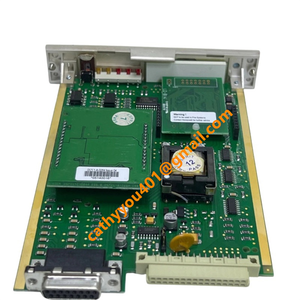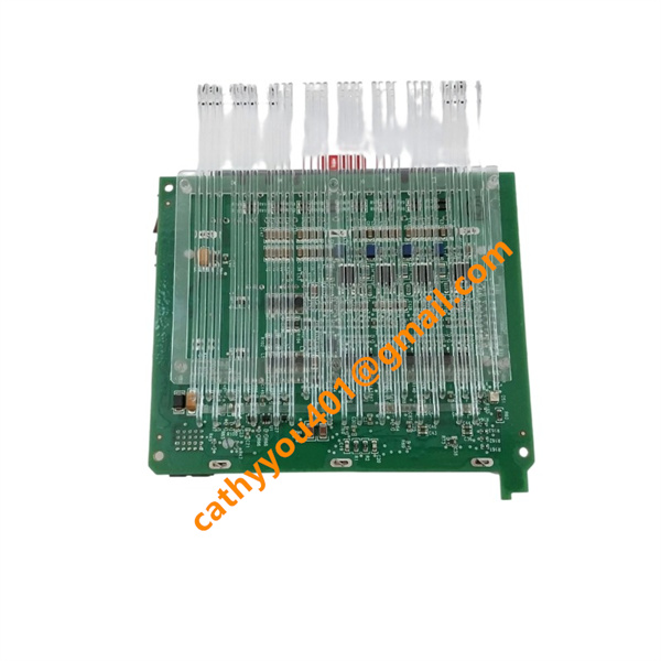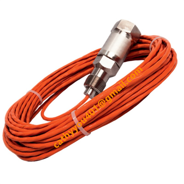





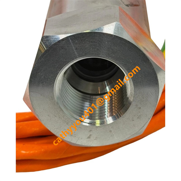
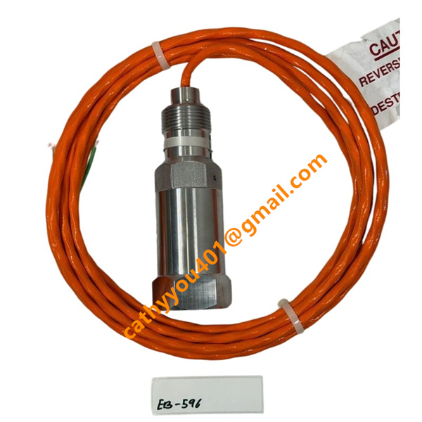







Description
-
BrandHONEYWELL
-
ModelLG1093AA24
-
Product NameIndustrial Ultraviolet (UV) Flame Sensor / Flame Detector
-
Place of OriginUnited States
-
HS Code8543709990
-
Dimensions120 mm × 85 mm × 60 mm
-
Weight0.8 kg
-
Operating Temperature-40 °C to +177 °C
-
Storage Temperature-45 °C to +185 °C
-
Part Number261A1812P012
-
Warranty12month
-
Product StatusNew and original
Voltage & Current Specifications of HONEYWELL LG1093AA24 (261A1812P012)
1. Operating Power Voltage
Rated supply voltage: 24 V DC
Working voltage range: 22 V DC ~ 28 V DC
2. Operating Current
Typical working current: 15 mA
Maximum operating current: 20 mA
3. Output Contact Rating
Output type: SPDT relay contact
Max load voltage: 24 V DC
Max load current: 0.2 A

HONEYWELL LG1093AA24 (261A1812P012) Installation Method
1. Pre-installation Preparation
Fully power off the flame monitoring system before starting installation. Check the sensor body and fused silica lens for scratches, dirt or damage that may affect detection performance. Inspect the 3/4-inch NPT thread for intactness. Select a suitable mounting spot with a clear, unobstructed view of the burner or furnace flame. Keep the sensor away from barriers, strong light, direct high-temperature flame exposure and heavy electromagnetic interference to prevent false alarms and detection errors.
2. Sensor Mounting Installation
The sensor uses a standard 3/4-inch NPT internal thread for mounting. Align the sensor with the reserved mounting base, turn it clockwise and fasten it moderately. Do not over-tighten to prevent thread or housing damage. Adjust the sensor angle so the UV detection window faces the flame area directly with no blind spots. Make sure the sensor is securely fixed and free of loosening or vibration during operation.
3. Field Wiring Connection
Remove the rear wiring cover of the sensor. Complete 24 V DC power and relay signal wiring strictly per the official circuit diagram. Ensure correct polarity and no short circuits, open circuits or loose connections. Apply certified explosion-proof fittings in hazardous explosive areas. Fully seal all wiring ports to meet IP65 and explosion-proof standards, avoiding dust and moisture ingress.
4. Pre-power-on Inspection
Double-check the sensor’s installation angle and fixing stability. Confirm all power and signal wiring is correct and safe with no potential circuit risks. Ensure the lens is clean and unblocked. Verify the on-site temperature, humidity and pressure comply with the sensor’s rated working conditions, and the installation area meets explosion-proof requirements.
5. Power-on Test & Commissioning
Re-power the system after all checks are finished. Observe the sensor operating status. Perform flame simulation or on-site combustion tests to confirm the sensor can normally detect flames and trigger accurate alarms when flame loss happens. Ensure stable signal operation without false triggering to complete the whole installation and commissioning work.