













Description
-
BrandBently Nevada
-
Model1900/65A
-
Product NameGeneral Purpose Equipment Monitor
-
Country of OriginUnited States
-
HS Code85389090
-
Dimensions196.9mm×149.4mm×74.4mm
-
Weight0.77 kg
-
Operating Temperature-20 ℃ ~ +70 ℃
-
Storage Temperature-30 ℃ ~ +90 ℃
-
Power Supply24VDC
-
Warranty12 month
-
Product StatusNew and original
Bently Nevada 1900/65A Product Introduction & Technical Specifications
Electrical Parameters
Rated Power Supply: 18–36 VDC wide-range DC input
Typical Operating Current: 0.35 A @ 24 VDC
Max Operating Current: 1.0 A
Typical Power Consumption: 8.5 W; Maximum 14 W
Dynamic Vibration Inputs: 4 channels, 25 kHz bandwidth, 24-bit high-precision ADC
Supported sensors: Eddy current probes, 2/3-wire accelerometers, velocity transducers
Temperature Inputs: 4 channels
Supported sensors: Type E/J/K/T thermocouples, 2/3-wire RTDs
Alarm Relay Outputs: 6 isolated programmable dry-contact relays, supporting voting logic
Analog Recorder Outputs: 4 configurable 4–20mA isolated process outputs
Buffered Signal Output: 4 built-in buffer ports for portable vibration tester connection
Communication Interfaces1. RS232/RS485 Modbus RTU (software configurable)
2. Optional Ethernet Modbus TCP gateway
Event Storage: Non-volatile memory, stores up to 200 time-stamped fault records
Insulation Strength: 2000 VAC isolation between power, signal and ground circuits

1900/65A Bently Nevada Core Product Advantages
1. Multi-Signal Integrated Monitoring: Simultaneous vibration, displacement, speed and temperature measurement in one compact unit, reducing cabinet space and spare part costs.
2. Mature High-End Monitoring Technology: Adopts the same stable signal processing circuit as 3500 rack monitoring system, higher measurement accuracy than single-function transmitters.
3. Flexible Dual-Stage Alarm Logic: Independent Alert (warning) and Danger (trip) thresholds for each variable; 6 relays support combined channel voting interlock for automatic equipment shutdown.
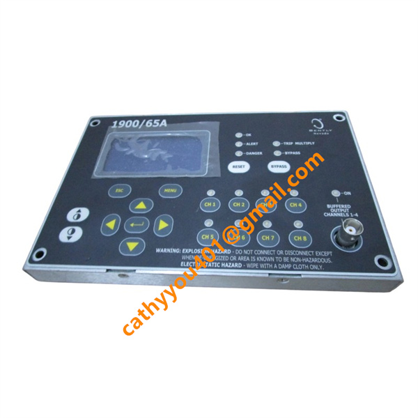
4. Remote Detachable Display: LCD keypad module can be mounted up to 75 meters away, convenient for on-site inspection without opening control cabinet doors.
5. Rich Digital Communication Options: Optional Modbus TCP/RTU realizes two-way data interaction with mainstream DCS, PLC and predictive maintenance software System 1.
6. Built-In Sensor Self-Diagnosis: Real-time detection of probe open circuit, short circuit and signal abnormality with instant alarm output.
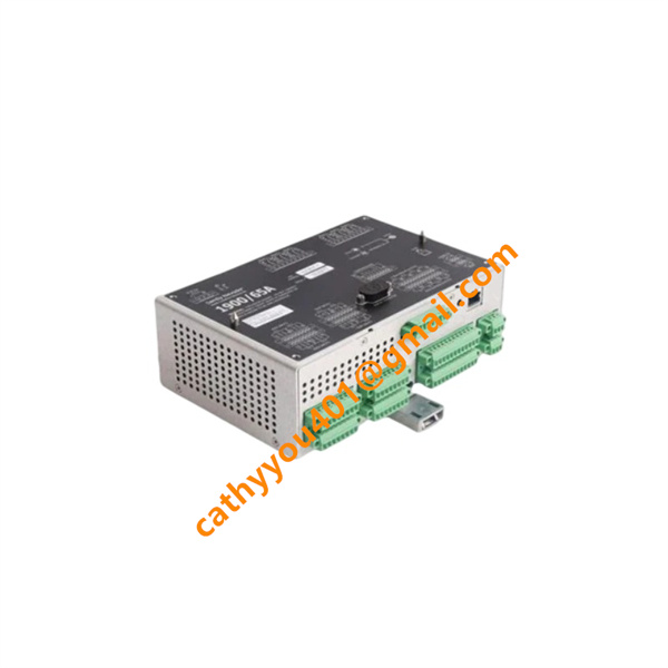
7. Multiple Installation Forms: Supports DIN rail and bulkhead mounting; optional IP66 waterproof housing for outdoor cabinet and field harsh environment installation.
8. Cost-Effective Standalone Design: No large rack system required, ideal for low-to-medium power auxiliary equipment monitoring in power, chemical, mining and water treatment industries.

1900/65A Bently Nevada Standard Wiring Method
Step 1 24 VDC Power Supply Wiring
Connect cabinet 18–36 VDC control power to dedicated power terminals; strictly distinguish positive and negative polarity. Install fuse at power inlet for short-circuit protection; single-end ground power cable shielding to cabinet protective earth bar.
Step 2 Vibration Sensor Signal Wiring
Use shielded twisted pair cables to connect proximity probes, accelerometers or velocity sensors to 4 dynamic input terminals. Separate weak sensor cables from high-power AC wiring to avoid electromagnetic interference; single-ended ground cable shield at cabinet earth bar only.
Step 3 Temperature Sensor Wiring
Route thermocouple/RTD wires to 4 temperature input terminals; use dedicated compensation cables for thermocouple measurement to guarantee temperature precision.
Step 4 Alarm Trip Relay Output Wiring
Wire 6 relay dry contact terminals to cabinet alarm annunciators and equipment shutdown interlock loops. Relays provide passive dry contacts without internal power; external control power must be configured separately for trip circuits.
Step 5 4-20mA Analog Output Wiring
Connect 4 analog output channels to DCS/PLC analog input modules; match external loop resistance per system drawing to ensure stable remote signal transmission.
Step 6 Modbus Communication Wiring
RS485 RTU: Double-shielded twisted pair for A/B terminals, install 120Ω matching resistor at the end of communication bus.
Ethernet Modbus TCP: CAT5e shielded network cable connected to RJ45 port, ground cable shield to cabinet earth.