













Description
-
BrandGE
-
Model489-P1-H1-20-E
-
Product NameGenerator Management Protection Relay
-
Dimensions178 mm × 145 mm × 220 mm
-
Weight2.6 kg
-
Place of OriginUnited States
-
HS Code85363000
-
Operating Temperature-20 ℃ to +60 ℃
-
Storage Temperature-40 ℃ to +85 ℃
-
Power Supply0.3 A
-
Warranty12 month
-
Statusnew in stock
Working Principle of 489-P1-H1-20-E GE Multilin
The 489-P1-H1-20-E is a microprocessor-driven digital generator management relay designed for both synchronous and induction generators. It continuously samples real-time electrical and temperature signals delivered from CT, VT and RTD inputs. The internal DSP chip computes measured parameters, compares these values against user-defined protection setpoints, and triggers alarm or trip operations via onboard logic once abnormal conditions are identified.
The relay acquires 1A secondary phase current signals from current transformers, three-phase voltage and neutral voltage signals from voltage transformers, stator and bearing temperature data from RTD sensors, as well as dry-contact status signals from binary inputs such as breaker auxiliary contacts, valve position switches and limit switches. All incoming analog signals go through filtering and analog-to-digital conversion before being processed by embedded calculation algorithms.
For differential protection, it implements dual-slope stator differential logic equipped with CT saturation detection and directional supervision. This mechanism differentiates internal stator short-circuit faults from external system disturbances and prevents nuisance tripping triggered by CT saturation under heavy external fault conditions. Its 100% stator ground fault protection locates faults by evaluating the balance of third-harmonic voltage between the generator terminal and neutral point, combined with residual ground current measurement.
Thermal protection is realized through a dynamic thermal model. It integrates phase current, negative-sequence unbalanced current and physical temperature feedback from RTDs to simulate heat accumulation within the stator and rotor. Inverse-time thermal curves are applied to avoid overheating damage, and thermal memory is maintained even after faults are cleared.
A full suite of protection elements including overcurrent, overvoltage, undervoltage, overfrequency, underfrequency, reverse power, loss-of-excitation and out-of-step protection operate individually or in coordination. Each protection function features adjustable pickup thresholds, time delays and selectable action modes for alarm or breaker tripping.
Onboard programmable logic enables generator sequence control, synchronism check, breaker failure monitoring and shutdown interlock functions. When a trip command is generated, its Form C relay outputs activate the breaker trip coil or the field de-excitation circuit.
This device also embeds metering, event logging and oscillography capabilities. Operational data, event records and fault waveform captures can be transmitted to SCADA systems and EnerVista software through Modbus RTU over RS485 or Modbus TCP over Ethernet. IRIG-B time synchronization guarantees uniform timestamps for all fault records.
Selected real-time parameters such as current, voltage, power and temperature can be transmitted via 4–20 mA analog outputs to PLCs or chart recorders for remote visualization and monitoring.

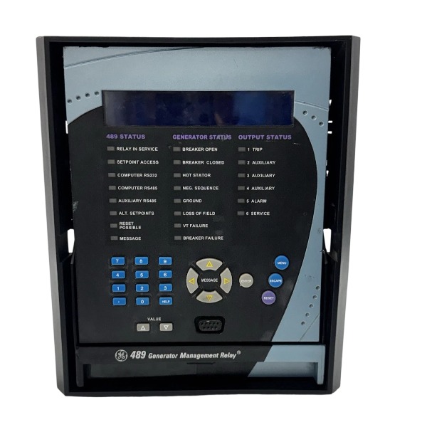
The 489-P1-H1-20-E is a generator management relay, and the P1 variant is designed for 1A CT secondary circuits.
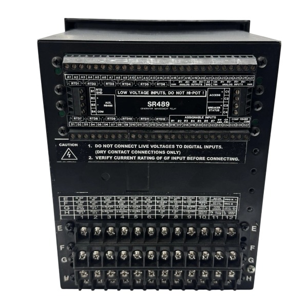
Control power terminals: Apply 70–265V AC or 90–300V DC to the control power terminals. AC and DC power supplies cannot be used simultaneously. The protective earth terminal must be connected to the cabinet star grounding point.
Phase current CT inputs: The secondary windings of three-phase 1A-rated CTs are wired to the Ia, Ib and Ic terminals. Always short-circuit CT circuits before disconnection; an open-circuited CT secondary is strictly prohibited. The neutral or ground-fault CT is wired to the residual current input terminals.
VT voltage inputs: Three-phase generator voltage signals from voltage transformers are connected to Va, Vb, Vc and the Vn neutral terminal. The VT secondary circuit requires reliable grounding, and there is no built-in fuse on the VT input channel.
RTD temperature inputs: 2-wire or 3-wire RTD sensors can be connected to the dedicated RTD terminals to monitor stator winding and bearing temperatures. The 3-wire connection method is preferred to minimize measurement errors caused by lead resistance.
Digital binary inputs: It provides 16 optically isolated binary inputs, which support 24–250V DC wet contacts. All inputs share a common terminal. Dry contacts from breaker auxiliary switches, position feedback switches and limit switches can be connected to these points.
Relay output contacts: 6 Form C relay outputs (NO/NC/COM) are available. The trip relay contact is wired in series with the breaker trip coil for tripping control, while alarm contacts are routed to local alarm indication loops. Comply with trip supervision wiring rules when the TCS function is activated.
Analog outputs: 20 channels of 4–20mA analog outputs are provided. These outputs adopt loop-powered wiring and connect to analog input modules of PLCs or recording devices.
Communication wiring: The RS485 terminals support Modbus RTU protocol; use twisted shielded pair cable with single-point shielding grounding. The rear RJ45 Ethernet port supports Modbus TCP and DNP3.0 over 10BASE-T cables. The front RS232 port is reserved for local commissioning with EnerVista software.
IRIG-B time sync terminal: Connect the IRIG-B timing signal to synchronize timestamps for event logs and oscillography records.
General wiring precautions: Route CT/VT high-signal cables, control cables and communication cables separately. Use shielded cables for analog and communication circuits. Fasten all terminals to the recommended torque value. It is recommended to install test blocks for CT and VT injection testing without removing existing wiring.

FAQ for GE 489-P1-H1-20-E Multilin 489 Generator Management Relay
Q1: What is GE 489-P1-H1-20-E?
A: The GE 489-P1-H1-20-E is a Multilin 489 generator management relay, designed for protection, monitoring and control of small to medium generators and prime movers in power systems.
Q2: What protection functions does GE 489-P1-H1-20-E provide?
A: It offers overcurrent, overvoltage, undervoltage, overfrequency, underfrequency, reverse power, loss of excitation and thermal overload protection for generators.
Q3: What communication interfaces does the 489-P1-H1-20-E support?
A: This relay supports Modbus RTU and DNP3 protocols, with RS485 port for connecting to SCADA, HMI and distributed control systems for remote data reading and control.
Q4: What are the typical applications of GE 489-P1-H1-20-E?
A: It is widely used in hydro generators, diesel generator sets, cogeneration plants, industrial powerhouses and utility backup power systems.
Q5: Can GE 489-P1-H1-20-E record fault data?
A: Yes, it includes fault event recording and oscillography function, helping engineers analyze trip causes after generator faults occur.
Q6: Is GE 489-P1-H1-20-E an obsolete model?
A: The Multilin 489 series is an older legacy relay. We supply tested surplus and refurbished units as replacement spares for existing generator protection cabinets.

DS200TDAH1BHD
DS200TCRAG1ACC
DS200DTRAG1AAA
DS200DTBBG1ABB
DS200SDCCG4AFD
DS200TCDAG1BDB
IS220PTURH1B
C60G01HCHF8FH6PM8FP6PU6PWXX
DS200TCQCG1BHF


.jpg)

.jpg)
.jpg)
.jpg)







