




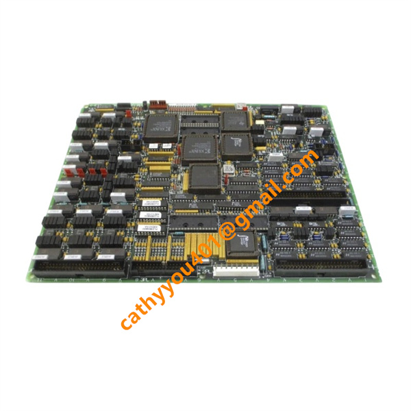
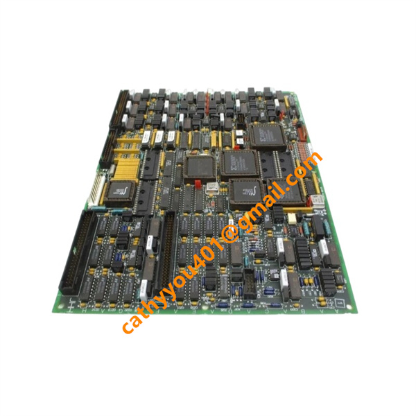







Description
-
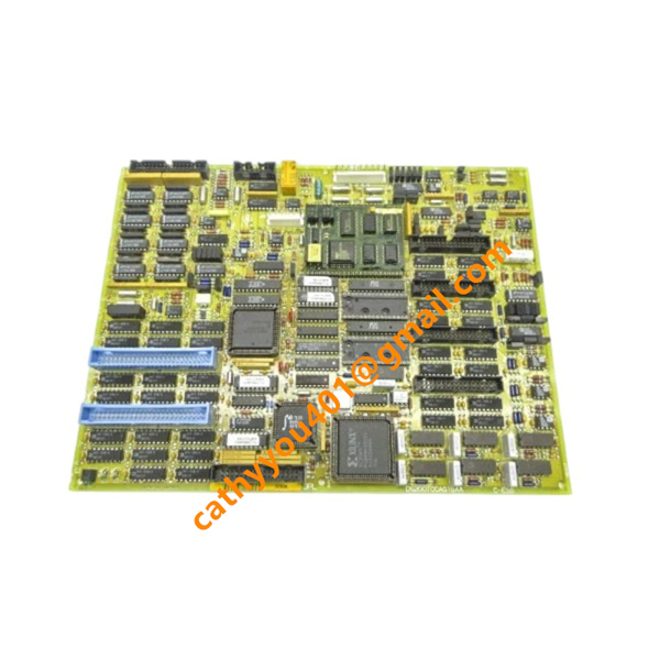
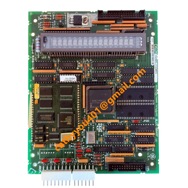
BrandGE
-
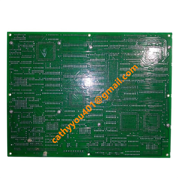
ModelDS200TCCBG1BED
-
Product NameTC2000 Common Extended Analog I/O Board
-
Place of OriginUnited States
-
HS Code85389091
-
Dimensions260 mm × 164 mm × 28 mm
-
Weight0.57 kg
-
Operating Temperature-20°C ~ +60°C
-
Storage Temperature-40°C ~ +85°C
-
Power Supply24 VDC
-
Warranty12 month
-
Product StatusNew and original
Backed by abundant in-stock inventory and nearly 20 years of industry experience, our company stands as a leading player in the industrial control sector.We offer an extensive range of industrial control products covering numerous models. Should you have any other requirements, please feel free to contact us, and we will respond to you promptly.
Our main brand:
1.ABB's module cards, touch screens, controllers, etc., such as PP846 touch screen, IGCT starting with 5SHY, PM starting controller, AI, DO starting input/output module, SP starting Bailey module, etc
2.GE's module card CPUs, such as VMIC starter, IS200, IS215, IS400, IS420 series, etc,
3.Emerson's card components and EPRO probes, Westinghouse 1C series, Honeywell CC series, Schneider 140 series, Envision full series, Bentley 3500 series, Rexroth motors and drives, and Foxboro small modules.
Analog Inputs
Voltage Input: ±10 VDC
Current Input: 4–20 mA, 0–1 mA
Special Inputs: RTD temperature signals, generator voltage & line current monitoring signals
Channel Quantity: 16 analog input channels
Input Connector: JHH
Analog Outputs
Output Current Range: 0–20 mA (max 20 mA per channel drive capacity)
Board Power Specifications
Operating Power Supply: 24 VDC
Typical Operating Current: 300 mA @24VDC

1. Pre-Operation Inspection
Ensure the 24 VDC power supply operates within the rated range without overvoltage or undervoltage fluctuations. Check the JHH connector wiring for secure connection, and eliminate short-circuit and open-circuit risks. Verify that technical parameters of field transmitters, sensors and load equipment comply with standard 4–20 mA and voltage signal specifications.
2. Installation and Power-On Procedure
Securely install the board on the GE Speedtronic Mark V system backplane to guarantee stable backplane electrical contact. Complete field signal wiring strictly in accordance with official channel definition standards. After thorough wiring inspection, power on the system; the board will initiate automatic self-diagnostics. Steady normal LED status indicates the board is in standby and ready for operation.
3. Standard Operating Functions
The board acquires and conditions field analog signals including ±10 VDC voltage, 4–20 mA current, RTD and thermocouple signals in real time. It converts processed analog signals into digital data and uploads valid data to the system controller. Meanwhile, it receives digital control commands from the system and outputs standard analog signals to precisely drive on-site actuators and regulating valves. It also supports real-time data recording and remote communication to facilitate system operational monitoring.
4. Routine Maintenance Requirements
Maintain a dust-free and well-ventilated operating environment for the board to prevent performance degradation or damage caused by excessive temperature. Regularly inspect wiring firmness and signal loop stability to ensure continuous and accurate signal transmission. Periodically analyze historical operation data to identify potential abnormal risks and realize predictive maintenance.
5. Fault Handling and Power-Specification Rules
A flashing fault LED signals abnormal signal transmission, loop failure or self-diagnostic errors. Prioritize troubleshooting external wiring and field devices for fault isolation. For disassembly and daily maintenance, cut off the field loop power first, followed by the system power supply. Hot swapping of the board during system operation is strictly prohibited to prevent permanent module damage.
Frequently Asked Questions (FAQ)
1.How fast will you reply to my inquiry?
We process all inquiries efficiently and will respond promptly once we receive your message.
2.Do you carry large inventory of industrial control parts?
We maintain massive ready stock of mainstream automation spare parts to shorten lead times.
3.Can you source discontinued or obsolete PLC & DCS modules?
Absolutely.
We specialize in sourcing hard-to-find, obsolete and out-of-production industrial control components.
4.Do you inspect goods before shipment?
Every product undergoes thorough inspection before packing and dispatch.
5.Can you ship orders worldwide?
We provide global shipping with flexible logistics for urgent and regular orders.
6.What payment methods are available?
We accept multiple secure payment options. Please contact our sales team for detailed terms.