





33222742AB814E55AE196B2974486F2B.jpg)
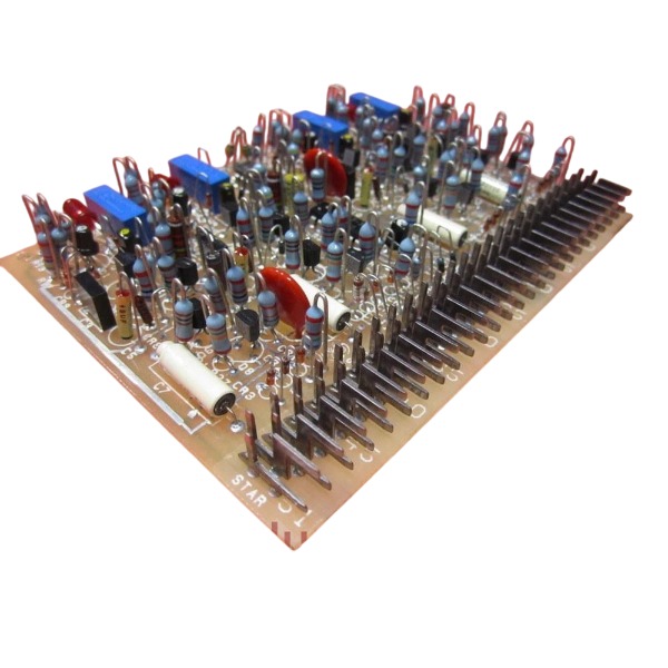







Description
-
BrandGE
-
ModelIC3600STDC1
-
Product NameSpeedtronic Turbine Control Circuit Board
-
Place of OriginUnited States
-
Customs HS Code8538900000
-
Power Supply0.75A
-
Dimensions275mm × 218mm × 32mm
-
Weight1.15kg
-
Operating Temperature-20℃ to +70℃
-
Storage Temperature-40℃ to +85℃
-
Warranty12 month
-
Product Statusnew brand
IC3600STDC1 GE Signal Conditioning Board Technical Specifications
Input:
Supports analog sensor input and discrete logic input channels. It receives unprocessed field-transmitted sensor signals as well as low-amplitude logic signals from the main control rack, and carries out filtering, level conversion and signal conditioning to adapt raw field signals to internal system signal standards.
Output:
Provides conditioned analog output and buffered logic output. After signal processing, standardized and stabilized signals are transmitted to core main-logic circuit boards, supporting turbine real-time status monitoring, parameter acquisition and safety interlock logic judgment.
Compatible Systems:
Fully compatible with GE Mark I Speedtronic and GE Mark II Speedtronic gas turbine and steam turbine control platforms, designed as a native plug-in module for these legacy turbine control racks.
Compatible Software:
Works with original GE Speedtronic legacy firmware. No separate dedicated application software is required. Functional configuration and parameter setting are completed through on-board hardware jumpers together with the built-in turbine control logic of the host system.
Supply Voltage:
Operating supply voltage ranges from 10-30 VDC. Nominal working voltage inside Mark I / Mark II card rack is 24 VDC.
Current:
Typical board power consumption ranges from 120 mA to 200 mA. Input and output signal current operates at low milliampere level; the signal ports cannot directly drive high-power field loads.
Operating Temperature:
-40℃ ~ +85℃. Adopts plug-in modular PCB design, intended for installation inside standard Speedtronic card rack.

IC3600STDC1 GE Signal Conditioning Board Operating Procedures
Safety Preparations: Shut down power to the Mark I / Mark II Speedtronic turbine control rack and dissipate residual stored energy. Complete lock-out and tag-out procedures. Ensure the system is fully offline to avoid unintended turbine trip events and electrical safety risks.
Pre-installation Inspection: Perform a comprehensive visual inspection on the IC3600STDC1 printed circuit board. Check for burn marks, defective components, fractured solder points and corroded connectors. Confirm on-board jumper configurations strictly match the turbine control logic design specifications.
Card Rack Installation: Line up the board’s edge connector with the assigned slot within the Speedtronic rack. Insert the module smoothly and tighten the locking screw to guarantee stable electrical contact between gold-plated pins and the system backplane.
Wiring Connection: Route field-sourced analog sensor cables and discrete logic input wires to their specified terminal positions. Connect output terminals to subsequent main-logic circuit boards. Inspect all wiring harnesses for short-circuits, open-circuit conditions and reversed polarity connections.
Pre-power-on Verification: Utilize a multimeter to test resistance values for power circuits and signal loops. Make certain no short-circuit occurs between power rails and protective ground. Re-validate jumper positions and overall wiring correctness one more time.
Power-up Commissioning: Re-energize the control rack gradually. Keep monitoring the board’s working voltage to maintain it within the 10-30 VDC operating range, with 24 VDC as the standard rack nominal voltage. Watch out for overheating, unusual noises or other abnormal phenomena.
Signal Input Functional Test: Feed analog sensor signals and discrete logic signals into corresponding input channels. Take measurements of conditioned output signals so as to validate proper performance of level shifting and signal filtering features.
System Integration Validation: Integrate the board into the complete Speedtronic control system. Run simulation tests for turbine monitoring parameters and safety interlock logic. Verify that converted signals can be accurately captured and processed by upstream main control modules.
In-service Condition Monitoring: While the turbine system remains operational, regularly evaluate input-output signal integrity, module surface temperature and power draw. Log any signal drift or anomalous alarm events for later reference.
Board Removal for Maintenance or Replacement: De-energize the entire system and enforce lock-out tag-out protocols. Disconnect field wiring terminals, release the locking screw, then pull the board gently out of its slot. Take care not to bend or damage delicate backplane pins.
Post-job Documentation: Record installation timestamp, detailed jumper settings, measured electrical parameters and all test outcomes. Retain these documents to support future fault diagnosis and periodic preventive maintenance activities.

DS200TDAH1BHD
DS200TCRAG1ACC
DS200DTRAG1AAA
DS200DTBBG1ABB
DS200SDCCG4AFD
DS200TCDAG1BDB
IS220PTURH1B
C60G01HCHF8FH6PM8FP6PU6PWXX
DS200TCQCG1BHF


.jpg)


.jpg)
.jpg)







