




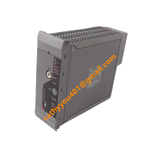
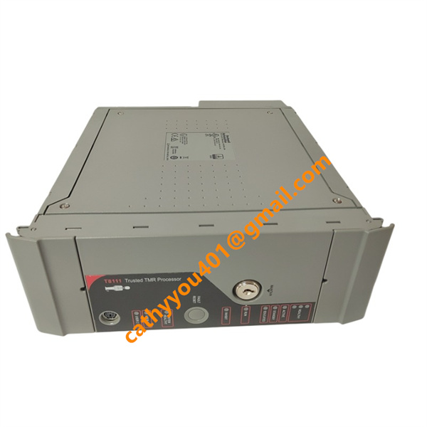







Description
-
BrandICS TRIPLEX
-
ModelT8111C
-
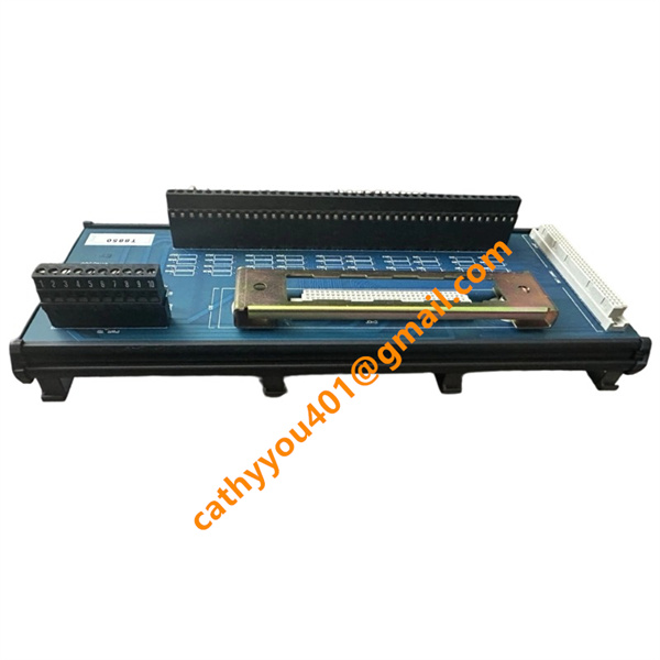
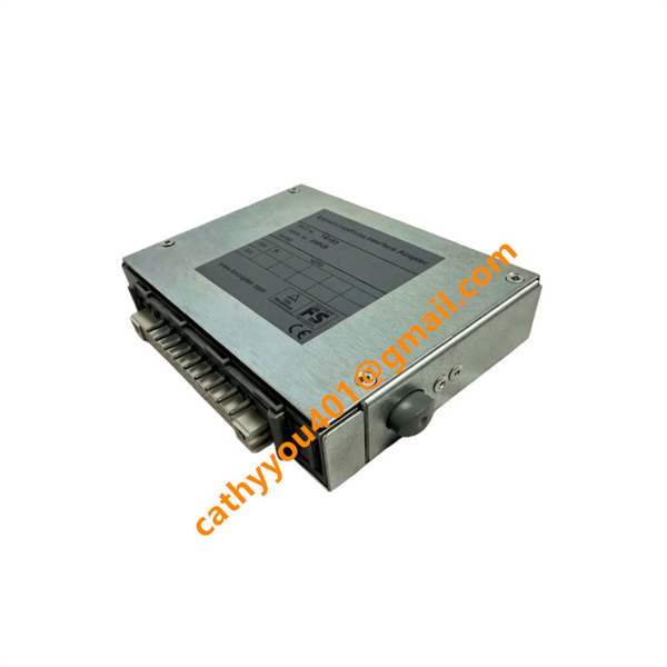
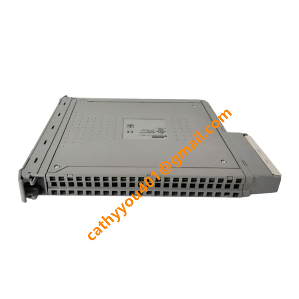
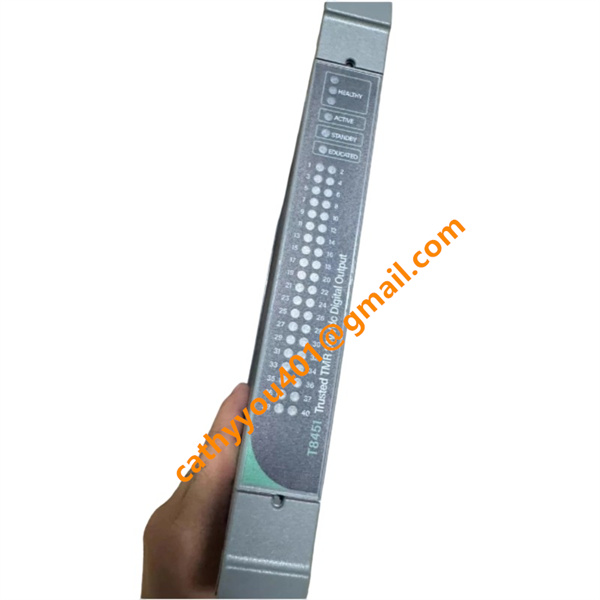
Product NameTrusted TMR Main Processor Module
-
Country of OriginUnited States
-
HS Code85389090
-
Dimensions270mm×93mm×303mm
-
Weight1.92 kg
-
Operating Temperature0 ℃ ~ +60 ℃
-
Storage Temperature-40 ℃ ~ +85 ℃
-
Power Supply24 vdc
-
Warranty12 month
-
Product StatusNew and original
ICS TRIPLEX T8111C Product Introduction & Technical Specifications
Electrical Parameters
Rated Supply Voltage: 24 VDC (operating range: 20 VDC ~ 32 VDC)
Typical Operating Current: 620 mA at 24 VDC
Total Power Consumption: Max 15 W
Core Processor: 3 independent 32-bit floating-point CPUs, 50 MHz main frequency
Memory: 1 MB RAM + 2 MB Flash non-volatile program storage
Backplane Bus: Trusted dedicated TMR inter-module communication bus
External Communication Interfaces1. Ethernet: Modbus TCP/IP for HMI & DCS connection
2. RS485: Modbus RTU auxiliary communication
3. RS232: Local diagnosis & configuration port
4. IRIG-B: Precision time synchronization input
Safety Certification: IEC 61508 SIL 3, TÜV, UL, CE
Isolation Grade: 2500 VAC isolation between power, signal and ground circuits

ICS TRIPLEX T8111C Core Product Advantages
1. 3-2-0 TMR Fault-Tolerant Architecture: Three independent CPU channels with hardware voting logic; single channel fault will not interrupt control output, eliminating single point of failure and meeting SIL 3 safety requirements.
2. Hot-Swap Online Replacement: Supports plug/unplug under powered rack; no program re-download or system reboot needed after replacement, greatly cutting maintenance downtime.
3. Full-Range Real-Time Self-Diagnosis: Automatically detects backplane communication errors, internal CPU faults, memory anomalies and bus short circuits; all faults stored with millisecond-level time stamp for SOE event tracking.
4. Complete Standard Communication Protocols: Integrates Ethernet TCP/IP and RS485 Modbus, seamless interconnection with mainstream DCS, PLC and monitoring HMI systems.
5. IRIG-B Precision Time Synchronization: Supports global unified time calibration, ensuring consistent time sequence for multi-module fault recording across the whole cabinet.
6. IEC 61131-3 Standard Programming: Compatible with Ladder Diagram, Function Block, Structured Text and other standard programming languages for flexible safety logic editing.
7. Rugged Industrial Design: Alloy casing and reinforced anti-vibration structure, stable operation in high-electromagnetic-interference chemical and power plant control rooms.
8. Unified Rack Compatibility: Standard single-slot size, fully matched with all T8300 series I/O modules without cabinet reconstruction.

ICS TRIPLEX T8111C Standard Wiring Method
Step 1 Rack Backplane Connection
Insert T8111C into the designated CPU slot of Trusted T8300 rack; push the module fully locked to connect rear backplane power and TMR communication bus. Confirm front panel status LEDs light normally after rack power-on.
Step 2 24 VDC Auxiliary Power Wiring
Connect cabinet 24 VDC control power to rack dedicated power terminals; strictly distinguish positive and negative polarity. Install 3A fuse at power inlet for short-circuit protection; single-end ground power cable shielding to cabinet protective earth bar.
Step 3 IRIG-B Time Synchronization Wiring
Use shielded twisted pair cable to connect IRIG-B clock signal source to module front time sync port; separate time signal wires from high-power AC cables to avoid signal distortion.
Step 4 Ethernet Communication Wiring (DCS/HMI)
Run CAT5e shielded Ethernet cable to module RJ45 port; connect cable shield to cabinet ground bar. Set fixed IP address via front RS232 diagnosis port before network communication.
Step 5 RS485 Modbus RTU Wiring
Adopt double-shielded twisted pair for RS485 A/B terminals; install 120Ω terminal matching resistor at the last module of communication bus to eliminate signal reflection interference.
Step 6 Local RS232 Diagnosis Wiring
Connect PC configuration tool to RS232 diagnosis port for program download, parameter calibration and fault history query during commissioning and maintenance.
Step 7 Cabinet Protective Grounding
Link module metal housing ground terminal and all signal cable shielding layers to cabinet common protective earth busbar to suppress static electricity and common-mode interference.
Step 8 Pre-Power-On Inspection
1. Check all wiring polarity, terminal tightness and no short circuit between bus terminals.
2. Verify rack backplane connectors are fully engaged without loose contact.
3. Complete offline program simulation test to validate safety interlock and trip logics before process commissioning.
4. Upload control program via RS232 port after power-on, confirm all communication links and front panel status indicators operate normally.