





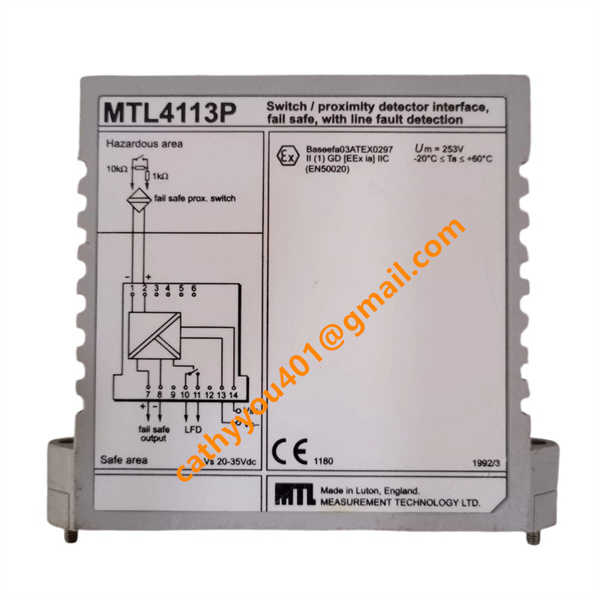
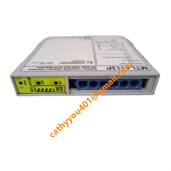







Description
-
BrandMTL
-
ModelMTL4113P
-
Product NameFail-safe Switch / Proximity Detector Isolating Interface Module with Line Fault Detection (LFD)
-
Place of OriginUnited Kingdom
-
HS Code8543709090
-
Dimensions20.5mm×110mm×115mm
-
Weight175 grams
-
Operating Temperature-20 ℃ to +60 ℃
-
Storage Temperature-40 ℃ to +70 ℃
-
Power Supply24VDC
-
Warranty12 month
-
Product StatusNew and original
Electrical Technical Specifications
Number of signal channels: Single isolated input channel
Field-side sensor supply output voltage for hazardous locations: 8.6 V DC, fitted with an integrated 1 kΩ current limiting resistor
Standard output voltage for safe side circuits: 24 V DC; output switches off when voltage drops below 5 V DC
Supported load impedance on the safe side output: 2.4 kΩ to 10 kΩ
Maximum output current under energized status: 11 mA
Short-circuit protection limiting current: 25 mA
Contact specification for LFD fault relay: 35 V AC/DC, 1 A resistive load
Main supply input voltage range (Vs): 20 V DC to 35 V DC
Typical power dissipation: 1.5 W with 24 V DC supply input
Operating supply draw: 70 mA at 24 V DC input, 80 mA at 20 V DC input, 65 mA at 35 V DC input
Dielectric isolation strength between safe circuits and hazardous intrinsically safe circuits: 253 V AC
Maximum intrinsically safe open-circuit output voltage (Uo): 9.7 V DC
Maximum permitted system voltage (Um): 250 V AC
Installation Guidelines of MTL4113P
Mounting Structure
MTL4113P adopts universal DIN rail mounting structure and fits standard 35 mm top hat DIN rails commonly used in industrial control cabinets. It can be mounted side by side with other modules from the MTL4000 series on one single rail, with no additional mounting accessories needed.
Step-by-Step Mounting Procedures
Pre-install and fix a horizontal standard 35 mm DIN rail inside the electrical cabinet.
Hook the upper lock tab on the module rear onto the top rim of the DIN rail.
Firmly push the module’s bottom against the rail until the bottom spring latch snaps into place for secure fixation.
Place neighboring MTL modules tightly against each other to optimize cabinet space; spacing between modules is unnecessary.
Wiring Partition Specifications
Field wiring terminals for hazardous area circuits are positioned on the top of the module, whereas connection terminals for safe-side control devices sit on the bottom. Cables for intrinsically safe hazardous circuits and safe circuits must be routed separately to meet isolation compliance standards.
Module Dismounting Procedure
Insert a flat-head screwdriver into the notch of the bottom spring latch, pull the latch down to unlock the mechanism, then lift the module upwards to take it off the DIN rail.
Environmental Installation Requirements
Reserve adequate airflow space around each module to prevent heat buildup. Avoid installing this unit inside compact fully sealed enclosures lacking heat dissipation structures. The continuous operating ambient temperature must remain between -20 °C and +60 °C.