












Description
-
BrandProSoft
-
ModelPLX51-HART-4I
-
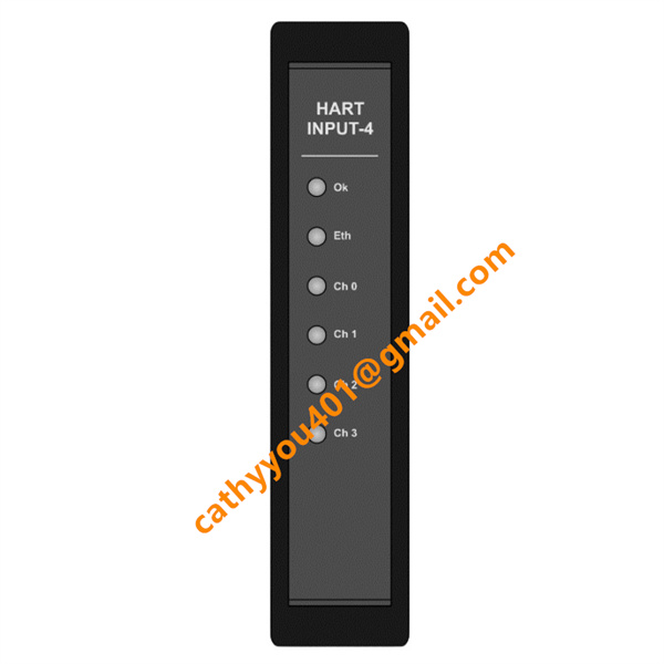
Product NameFour-channel HART Analog Input Industrial Ethernet Gateway Module
-
Country of OriginUnited States
-
HS Code85176290
-
Dimensions110mm(H)×40mm(W)×130mm(D)
-
Weight0.42kg
-
Operating Temperature-20°C ~ +70°C
-
Storage Temperature-40°C ~ +85°C
-
Power Supply24vdc
-
Warranty12 month
-
Product StatusNew and original
ProSoft PLX51-HART-4I Input Gateway Module
Electrical Parameters: Input Voltage & CurrentRated Power Supply Voltage: 10VDC ~ 28VDC (24VDC standard industrial power supply)
No-load Operating Current: 35mA @24VDC; 64mA @12VDC
Full Load Max Current (4 channels connected): 130mA @24VDC; 160mA @12VDC
Static Power Consumption: 0.9W (no field equipment); Max 4.3W under channel short-circuit condition
Analog Input Signal Range: 0~22mA, standard 4–20mA HART loop signal
ADC Sampling Resolution: 12-bit high precision
Input Loop Current Limit: 34mA per channel
Ethernet Port: 10/100Mbps auto-adaptive RJ45 interface, Auto-MDI/MDIX function
10. HART Channel Technical IndexTotal Channels: 4 isolated HART input channels
Network Mode: Point-to-point single instrument connection; Multi-drop mode supports up to 7 HART field devices per channel
Internal Loop Power Supply: Each channel supports passive two-wire HART transmitters without external power supply
Communication Protocol: HART 5 / HART 7 universal protocol version

ProSoft PLX51-HART-4I Detailed Wiring Instructions
The module adopts two separated terminal wiring terminals: 3-pin power terminal block and 2-pin independent terminal blocks for each HART channel, applicable for 18~24AWG wire gauge.
1. Power Supply Wiring (3-way Terminal Block)
Pin 1: DC24V Positive (+)
Pin 2: DC Negative / Common Ground (-)
Pin 3: PE Protective Earth Wire, must be connected to cabinet ground bar for EMC anti-interference requirement
2. Four HART Analog Input Channel Wiring
Each channel uses independent two-pin terminal, internal loop-powered design for two-wire HART transmitters:
Terminal Positive: Connect to positive pole of HART transmitter signal line
Terminal Negative: Connect to transmitter negative pole and field loop ground
Point-to-point mode: Single HART instrument connected on one channel; Multi-drop mode: Multiple HART devices parallel connected on same channel bus
3. Ethernet Communication Wiring
RJ45 Ethernet port connects to industrial switch/PLC Ethernet interface via shielded CAT5E industrial network cable; shield layer needs single-end grounding to restrain transmission interference.
4. Installation Operation
Pull down DIN rail buckle with flat screwdriver, buckle the module on 35mm standard DIN rail and lock the buckle upward to finish mechanical fixing.

ProSoft PLX51-HART-4I Detailed Wiring Instructions
The module adopts two separated terminal wiring terminals: 3-pin power terminal block and 2-pin independent terminal blocks for each HART channel, applicable for 18~24AWG wire gauge.
1. Power Supply Wiring (3-way Terminal Block)
Pin 1: DC24V Positive (+)
Pin 2: DC Negative / Common Ground (-)
Pin 3: PE Protective Earth Wire, must be connected to cabinet ground bar for EMC anti-interference requirement
2. Four HART Analog Input Channel Wiring
Each channel uses independent two-pin terminal, internal loop-powered design for two-wire HART transmitters:
Terminal Positive: Connect to positive pole of HART transmitter signal line
Terminal Negative: Connect to transmitter negative pole and field loop ground
Point-to-point mode: Single HART instrument connected on one channel; Multi-drop mode: Multiple HART devices parallel connected on same channel bus
3. Ethernet Communication Wiring
RJ45 Ethernet port connects to industrial switch/PLC Ethernet interface via shielded CAT5E industrial network cable; shield layer needs single-end grounding to restrain transmission interference.
4. Installation Operation
Pull down DIN rail buckle with flat screwdriver, buckle the module on 35mm standard DIN rail and lock the buckle upward to finish mechanical fixing.