.jpg)
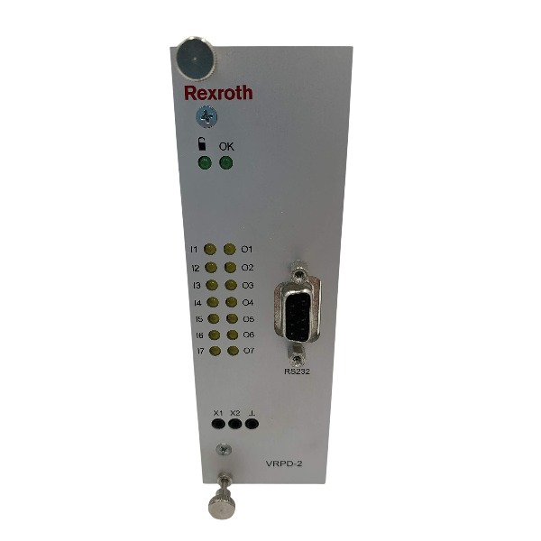







Description
-
BrandRexroth
-
ModelVT-VRPD-2-2X/V0/0-0-1
-
Product NameDigital Proportional Valve Amplifier
-
Place of OriginGermany
-
Customs HS Code8542319000
-
Part numberR901066987
-
Dimensions340 mm × 233 mm × 30 mm
-
Weight0.31 kg
-
Operating Temperature0 °C to 60 °C
-
Storage Temperature-20 °C to 80 °C
-
Warranty1 year
-
Product Statusbrand new
R901066987 VT-VRPD-2-2X/V0/0-0-1 Rexroth Digital Valve Amplifier
Power Supply Specifications
Operating Voltage: 24 VDC (allowable tolerance: -10% ~ +40%, valid range: 21–35 VDC)
Power Consumption: Typical operating current 1.5 A; standby current 270 mA
Protection Fuse: 4 A slow-blow fuse (onboard protection)
Input Signals
Analog Voltage Inputs
AI2, AI4, AI5 support differential ±10 V signal input, with input impedance ≥100 kΩ and 5 mV high resolution.
AI4: Main command setpoint input
AI2 / AI5: Auxiliary signal for upward/downward ramp control
Analog Current Input
AI6 is dedicated 4–20 mA main setpoint input, with 100 Ω input resistance and 5 µA resolution for accurate current signal acquisition.
Digital Binary Inputs
DI1–DI4: 4-bit binary grouping inputs, supporting switching of up to 16 groups of preset control parameters; logic threshold: 0–5 V (Logic 0), 16 V ~ UB (Logic 1)
DI5–DI9: Multi-functional configurable inputs for system enable, setpoint activation and custom trigger functions; single-channel maximum current 30 mA, with built-in short-circuit protection
LVDT Sensor Input
Built-in 5 kHz carrier frequency drive circuit, matching the valve’s built-in LVDT sensor, acquiring real-time spool position feedback to form closed-loop control.
Output Signals
Valve Coil Drive Outputs (Coil A / Coil B)
Adopts 5.7 kHz PWM high-frequency driving mode; single-coil maximum output current 2.5 A, with output residual ripple lower than 20 mV, ensuring stable valve action.
Analog Monitoring Outputs
AO1 and AO3 are 14-bit high-precision analog monitoring outputs (±10 V), supporting minimum 1 kΩ load. Used for real-time feedback of valve command setpoint and actual spool position values for external monitoring.
Digital Logic Outputs
DO1–DO7 are configurable logic outputs with 30 mA single-channel maximum current and short-circuit protection:
DO1: Coil A operating status indication
DO2: Coil B operating status indication
DO3: Spool position deviation alarm (out of tolerance window)
DO4–DO6: User-defined configurable outputs
Fault Status Output
Dedicated fault/normal signal output: outputs low level when faults occur (spool position deviation, LVDT circuit breakage, 4–20 mA signal loss and other abnormal conditions).
Supported Valves & Control Systems
Compatible Valves: Rexroth 4WRE6-2X and 4WRE10-2X series proportional directional valves with native LVDT spool feedback
Upper Control Device: PLC or motion controller with ±10 V analog / 4–20 mA current output or binary preset signal output
Operating Feature: Onboard independent closed-loop control, no reliance on external controllers; non-standard fieldbus slave device
Communication Protocols
Local RS232 Serial Port: For PC parameter configuration, debugging and diagnosis
Rexroth Proprietary Local Bus: Supports networking of up to 32 amplifiers, maximum transmission distance 280 m
Note: No support for standard industrial fieldbus protocols, including Profibus, EtherCAT and Profinet
Commissioning Software & Tools
Matching Software: BODAC (Bosch Rexroth Operator interface for Digital Axis Controller)
Software Part Number: SYS-HACD-BODAC-01 (R900777335)
Commissioning Cable: Null-modem RS232 dedicated cable (Model: VT-HACD-1X/03.0/HACD-PC, R900776897)
Core Functions: Valve model matching, gain and offset calibration, ramp parameter configuration, fault threshold setting, parameter backup restoration and real-time equipment diagnosis.

Installation Guide for Rexroth R901066987 VT-VRPD-2-2X/V0/0-0-1
1. Pre-Installation Preparation & Safety
Installation must be performed by qualified hydraulic and electrical technicians.
Cut off 24VDC power and fully depressurize the hydraulic system before operation.
Inspect the amplifier board for physical damage, burning or connector deformation.
Follow ESD protection rules: wear anti-static wristband and avoid touching chip pins and solder points.
Prepare required materials: 19-inch rack frame, 64-pin backplane connector, shielded LVDT/valve/signal cables, 24VDC power supply and RS232 null-modem cable for BODAC commissioning.
Standard cable requirements:
LVDT feedback: 4-core double-shielded cable, max length 50 m
Valve coil and analog signal: shielded twisted pair cable
2. Mechanical Installation
Install the Eurocard holder in a standard 19-inch cabinet, reserve cooling space, and keep away from heat sources and high-power equipment.
Operating cabinet temperature: 0 ~ 50°C.
Insert the amplifier steadily into the guide rail, fully connect with the 64-pin backplane, and fasten the front panel screw.
Reliably connect the rack protective earth (PE) to cabinet ground for EMC protection.
3. Wiring Specifications & EMC Rules
Separate different types of cables and avoid bundling to prevent interference: LVDT weak signal cable, valve PWM power cable, analog signal cable, 24VDC power and digital cable.
LVDT cable: Only ground the shield at the amplifier end; keep the valve end floating to avoid ground loop.
Valve coil cable: Shield layer connects to valve housing and cabinet ground.
3.1 Power Wiring
Rated input: 24 VDC (21~35 VDC allowable range)
Install 4 A slow-blow fuse for power circuit.
Follow positive/negative polarity; built-in reverse connection protection is available, but standard wiring is still required.
Do not share power with unisolated large inductive loads.
3.2 LVDT Feedback Wiring
Connect the 4-core shielded cable to the dedicated LVDT pins, strictly match 4WRE6/4WRE10 valve pin definition, to avoid feedback failure and alarms.
3.3 Valve Coil Wiring
Connect Coil A/B to the proportional valve solenoid coils. Single coil max continuous current: 2.5 A, 5.7 kHz PWM driving. Keep cable length within factory specification.
3.4 Analog I/O Wiring
Setpoint input: ±10 V differential or 4–20 mA
Auxiliary ramp input: ±10 V
Monitoring output AO1/AO3: ±10 V (min load 1 kΩ) for setpoint and actual spool position feedback
All analog signals use shielded twisted cables.
3.5 Digital I/O Wiring
DI1~DI9: 24V digital input for parameter selection, enable and trigger signals, max 30 mA per channel with short-circuit protection
DO1~DO7: Status and fault digital output, max 30 mA
Fault OK contact: For PLC alarm collection
3.6 Communication Interface
Front RS232 port: Connect PC for BODAC parameter configuration and diagnosis
Rexroth proprietary local bus: Support up to 32 amplifiers in series, max 280 m distance; **not compatible with Profinet / EtherCAT / Profibus**
4. Pre-Power-On Inspection
Check backplane pins for bending and short circuits.
Confirm no short circuit between power pins, signal pins and ground.
Verify LVDT and coil wiring consistency with drawings.
Complete cabinet grounding, keep hydraulic system depressurized for first power-on test.
5. Power-On Initial Check
Power on 24VDC and check front LED status, no overcurrent or power fault alarm.
Connect PC via RS232 and communicate with the amplifier through BODAC software.
Select matched valve model (4WRE6-2X / 4WRE10-2X).
Manually move valve spool to verify normal LVDT feedback.
6. Commissioning & Tuning
Configure signal type (±10 V / 4–20 mA), ramp parameters and DI preset parameter groups.
Calibrate closed-loop gain and offset of spool position in BODAC.
Set fault thresholds for LVDT breakage, signal loss and position deviation.
Test digital output and fault alarm function.
Complete no-load debugging first, then full-load hydraulic commissioning.
7. Final Documentation
Save and back up amplifier parameter files.
Record slot position, valve serial number, calibration data and fault definition.
Update cabinet wiring labels and project documents.
8. Key Installation Restrictions
Only compatible with 4WRE6/4WRE10 2X valves with LVDT spool feedback.
No hot-swap operation under powered status to avoid board and connector damage.
Do not lay inverter high-frequency cables in parallel with LVDT cables.
Local bus is Rexroth private protocol, cannot connect directly to standard PLC fieldbus ports.

HDS03.2-W075N-HS12-01-FW
VT-VPCD-1-1X/V0/1-P-1
MSK061C-0600-NN-M1-UG1-NNNN
VT-VPCD-1-18/V0/1-0-1
DKC03.3-040-7-FW