





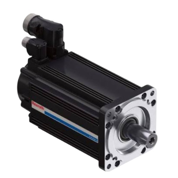







Description
-
BrandRexroth
-
ModelMSK100D-0300-NN-M2-BG0-RNNN
-
Product NameIndraDyn S MSK Permanent Magnet Synchronous Servo Motor
-
Place of OriginGermany
-
Customs HS Code85015200
-
Part numberR911311296
-
Dimensions285 mm × 130 mm flange, shaft diameter 32 mm
-
Weight22.8 kg
-
Operating Temperature0 °C to +40 °C
-
Storage Temperature‑20 °C to +70 °C
-
Warranty12 month
-
Product Statusnew
Inputs and Outputs of Rexroth R911311296 (MSK100D-0300-NN-M2-BG0-RNNN)
Power Input
3-phase AC power input: U, V, W, fed from servo-drive inverter output; rated voltage 400 VAC; rated phase current 24 A
PE protective earth terminal
Built-in Sensor Input (signal transmitted to servo drive)
Sin/Cos absolute multi-turn encoder signals: A, /A, B, /B, R, /R, data and clock lines; signal amplitude 1 Vpp-peak differential low-voltage signal
PT1000 temperature-sensor circuit: embedded inside stator winding, resistance signal without external power supply, for motor thermal monitoring
Holding-brake coil power input: 24 V DC nominal; typical coil current 0.65 A; electromagnetic holding brake for static shaft locking
Motor Output (Mechanical)
Rotor shaft mechanical output: rotational torque and speed transmitted to mechanical load through coupling

Fault Diagnosis Methods for Rexroth R911311296 (MSK100D-0300-NN-M2-BG0-RNNN)
Pre-diagnosis Basic Principle
Diagnosis shall follow this workflow: read drive alarm codes → inspect wiring and cables → carry out mechanical inspection → perform electrical measurement → validate parameters → conduct cross-component swap test. Complete power-off and full capacitor discharge before all hardware inspection and measurement activities.
Step 1: Drive Alarm Code Analysis via IndraWorks
Connect IndraWorks DS software to the servo drive, retrieve real-time alarm information and historical fault buffer data.
Typical encoder-related alarms include F2031, F229, F276 and E2077. These faults are usually caused by defective encoder cables, damaged connector pins, internal encoder failure or electromagnetic interference.
Overload and overtemperature alarms F8010, F8021 require inspection of actual load conditions, heat dissipation performance and the motor-integrated PT1000 temperature sensor circuit.
For power-circuit alarms such as phase loss and short-circuit, check motor winding integrity and insulation condition of power cables.
When brake-related alarms appear, verify 24 V DC brake power supply and operating status of the brake coil.
Step 2: Visual & Mechanical Inspection under Power-off Condition
Examine the motor housing for oil leakage, cracks, surface abrasion and impact damage caused by foreign objects.
After decoupling the motor from mechanical load, manually rotate the motor shaft. Smooth rotation without jamming, friction noise or knocking sound is expected. Stiff rotation implies bearing damage or internal rotor failure, which requires professional overhaul.
Check couplings, connecting flanges and mounting screws for looseness, and confirm proper coaxial alignment between the motor and driven machinery.
Ensure no excessive dust or oil contamination accumulates on the motor surface, which would impair heat dissipation.
Step 3: Cable and Connector Inspection
Check power and encoder cables for crushing, tensile stress and sheath damage. Separate these signal cables from high-power lines to minimize electromagnetic interference.
Disconnect power and encoder connectors, check pins for bending, oxidation, dirt or poor crimping, then firmly re-seat all connectors.
Verify shield grounding: cable shields shall be reliably earthed on both drive and motor sides.
Inspect holding-brake wiring for correct polarity and secure connections.
Step 4: Motor Electrical Measurement
Winding resistance test: measure U-V, V-W and W-U phase-to-phase resistance by multimeter. Three-phase resistance values should be well-balanced; significant deviation indicates winding open-circuit or inter-turn short-circuit.
Insulation resistance test: use a megohmmeter to measure resistance between each winding phase and motor housing. Low insulation resistance suggests dampness or insulation aging.
Holding-brake coil resistance measurement: compare measured resistance against the reference range shown on the nameplate. Open-circuit or short-circuit readings point to brake coil failure.
Temperature-sensor measurement: measure PT1000 resistance at the motor terminal box. Abnormal resistance readings indicate faults in the temperature-detection circuit.
Step 5: No-load and Load-separated Test
Disconnect the mechanical coupling and perform no-load jog test.
If the motor runs normally without load but reports faults under loaded conditions, root causes lie in mechanical overload, mechanical jamming, misalignment or excessive friction from driven equipment.
If faults persist even in no-load status, focus troubleshooting on the motor itself, connected cables or drive parameter settings.
Step 6: Encoder-specific Fault Diagnosis
For position drift, excessive position error and intermittent position jumps: reseat the encoder connector first, then replace the encoder cable for verification.
Utilize the oscilloscope function within IndraWorks to monitor Sin/Cos feedback signal amplitude. Distorted signal amplitude indicates encoder hardware damage.
In case of absolute encoder alarms, perform absolute position recalibration. Repeated identical alarms mean internal encoder damage, requiring factory repair.
Suppression of interference: optimize grounding arrangement, install ferrite cores on encoder cables and avoid parallel routing alongside power cables.
Step 7: Parameter and Environment Verification
Ensure the drive motor database correctly selects MSK100D-0300-NN-M2-BG0-RNNN; never apply mismatched motor parameter sets.
Review servo gains, acceleration/deceleration settings and position-error monitoring thresholds. Improper parameter configuration may trigger false overload or position alarms.
Check actual operating conditions to confirm continuous torque and peak torque do not exceed motor rated limits.
Step 8: Cross-swap Verification Method
Swap encoder and power cables with those from a known-good identical motor. If the fault migrates together with cables, the cables are defective.
If spare parts are available, substitute with a functional MSK100D motor. If the fault follows the motor unit, the motor hardware is damaged. If the fault remains unchanged, the issue originates from the drive or peripheral logic circuits.

HDS03.2-W075N-HS12-01-FW
VT-VPCD-1-1X/V0/1-P-1
MSK061C-0600-NN-M1-UG1-NNNN
VT-VPCD-1-18/V0/1-0-1
DKC03.3-040-7-FW


.jpg)







