





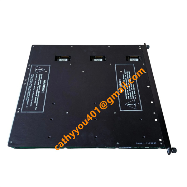
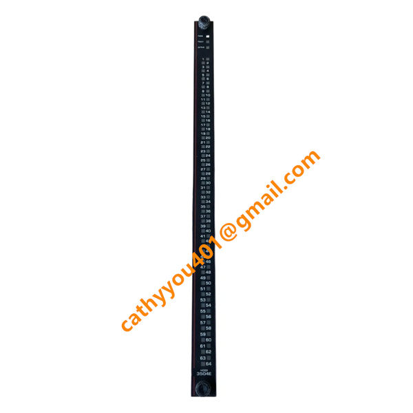







Description
-
BrandTriconex
-
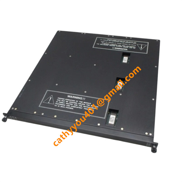
Model3504E
-
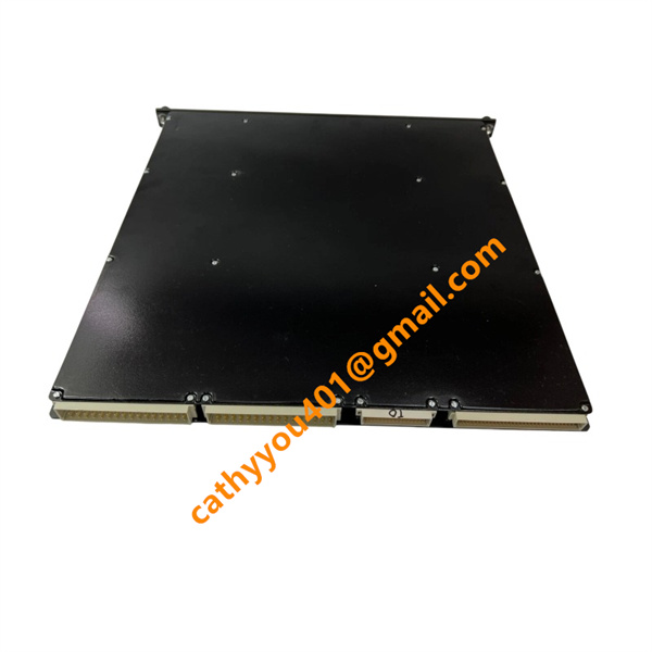
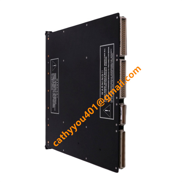
Product NameHigh Density Digital Input Module
-
Place of OriginUnited States
-
HS Code8537101190
-
Dimensions490 mm × 453 mm × 68 mm
-
Weight2.0 kg
-
Operating Temperature-40 °C to +70 °C
-
Storage Temperature-40 °C to +85 °C
-
Power Supply24VDC
-
Warranty12 month
-
Product StatusNew and original
Voltage & Current Specifications of Triconex 3504E
1. System Operating Voltage
Rated supply voltage: 24 V DC
Operating voltage range: 20 V DC ~ 72 V DC
2. Channel Electrical Parameters
Input signal hysteresis: 4 V DC / 7 V DC
Single channel input current: 20 mA typical
Input impedance: 10 kΩ
3. Power Characteristics
The module adopts TMR redundant power design, supporting wide-range DC power supply fluctuation. It features overvoltage and undervoltage self-protection to adapt to complex field power conditions.

Triconex 3504E Installation Method
Pre-installation Preparation
Shut down the entire SIS cabinet power completely and confirm there is no residual voltage to prevent personal injury and module damage. Check the 3504E module surface and ports to rule out damage, dirt and defects. Confirm the chassis slot fits the module, and clean the slot contacts for stable connection. Leave enough ventilation space at the installation position and keep the module away from heat sources and signal interference devices.
Module Chassis Installation
The module is equipped with anti-misplug mechanical keys to prevent installation in wrong slots. Align the 3504E with the empty I/O slot of the Triconex 3000/3000X chassis. Insert the module horizontally and push it firmly until it fully locks onto the backplane connector. Tighten the fixing screws on the module front panel to fix the module securely without shaking or loosening.

Terminal & Field Wiring
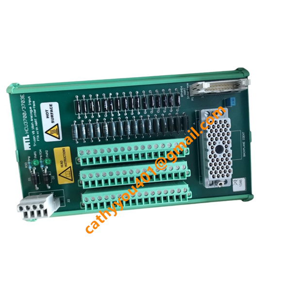
Use the special matching cable to connect the module to the External Terminal Panel (ETP). Connect all on-site 24 V DC digital input signals to the terminal panel strictly following the wiring diagram. Ensure correct wiring polarity, and no short circuit, open circuit or loose connection. Arrange all cables neatly, and do not squeeze, stretch or severely bend the cables.
Pre-power-on Inspection
Check that the module is fully inserted and firmly fixed. Confirm all cable connections are correct and complete. Make sure the module ventilation holes are free of blockages. The installation environment must be indoor, meet IP20 protection standard and have non-condensing humidity. Check the whole circuit to eliminate short-circuit risks.
Power-on & Functional Commissioning
Switch on the cabinet power and check if the module indicator lights work normally. This module supports hot-swap, which allows online replacement without shutting down the entire system. After the system completes initialization, test all signal channels and verify system configurations to ensure the module can normally collect field signals and detect faults.
Installation Notes
Do not plug or unplug the module under live power, except for approved hot-swap operations. Do not install the module in humid, dusty, corrosive or high-vibration working environments. Reserve enough heat dissipation space to ensure the module works stably within the rated temperature range. Install the module in the specified chassis slot in accordance with system configuration requirements to avoid mismatched installation.