




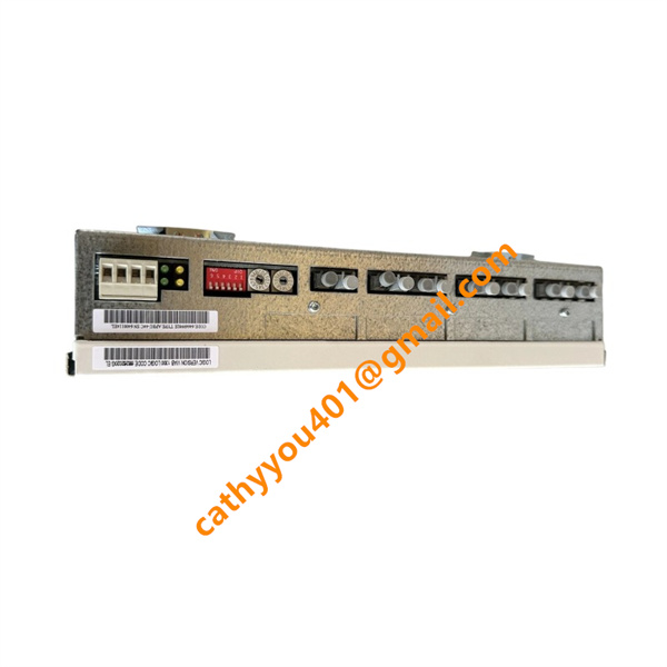

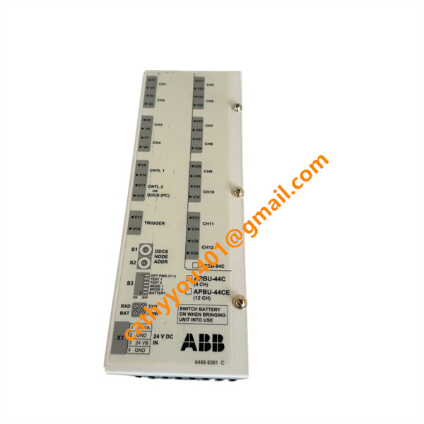







Description
-
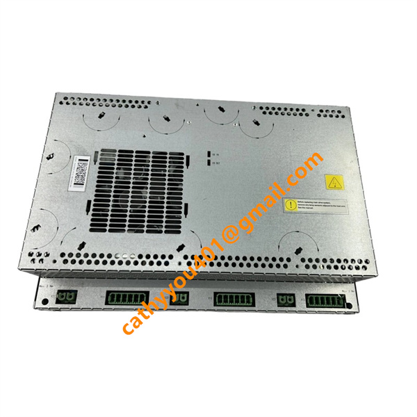
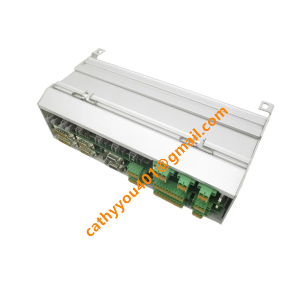
BrandABB
-
ModelAPBU-44C
-
Product NamePPCS Branching and Datalogger Unit
-
Place of OriginSweden
-
HS Code8537101190
-
Dimensions41 mm × 264 mm × 94 mm
-
Weight0.94 kg
-
Operating Temperature-20 °C to +70 °C
-
Storage Temperature-40 °C to +85 °C
-
Power Supply24vdc
-
Warranty12 month
-
Product StatusNew and original
Voltage & Current Specifications of ABB APBU-44C (PPCS Branching and Datalogger Unit, Part No.64669982)
1. Power Supply Voltage
Rated supply voltage: 24 V DC
Operating voltage range: 21.6 V DC ~ 26.4 V DC (±10% tolerance)
Only 24 V DC control power is supported, AC input is not allowed. Internal communication and data logging circuits are electrically isolated from the power supply circuit.
2. Power Consumption & Operating Current
Full-load power consumption: 10 W, rated operating current: approx. 0.42 A @ 24 V DC
Max inrush current: < 0.8 A
Standby power consumption: 6 W, standby current: approx. 0.25 A
3. Communication Bus Electrical Levels
PPCS fiber bus internal logic level: 3.3 V DC
DDCS differential signal level: 5 V DC
Full electrical isolation for optical ports, no signal crosstalk with power circuit.
4. Voltage Protection Thresholds
Over-voltage protection point: 27.0 V DC
Under-voltage lockout threshold: 19.0 V DC (stops signal distribution and data logging)
Isolation withstand voltage: 2500 V AC between power and communication interfaces
5. External Trigger Interface Ratings
Trigger input voltage range: 12–24 V DC
Max sinking current per channel: 10 mA
Max external signal source current: 20 mA (no auxiliary relay required)

ABB APBU-44C Installation Method
1. Pre-installation Preparation
Fully power off the entire drive cabinet and confirm no residual power to prevent electric shock or module damage. Choose a standard 35mm DIN rail position inside the cabinet. Leave enough space around the module for ventilation and keep it away from high-power heat-generating devices. Check the module appearance and ports to ensure no damage, dirt or missing parts.
2. DIN Rail Mounting
Align the APBU-44C with the 35mm DIN rail. Hang the top buckle on the rail, then push and press the module down firmly until the bottom spring buckle clicks and locks tightly. Give the module a slight shake to confirm it is fixed securely with no looseness or deviation.
3. Wiring & Fiber Connection
Wire the 24 V DC control power cable strictly by positive and negative polarity to avoid reverse connection. Plug ST-type multi-mode optical fibers correctly: connect V9/V12 ports to RDCU main unit, V1–V8 ports to ACS800 inverter/rectifier modules, and V13/V14 ports to external trigger devices. Arrange fibers neatly, and do not bend, twist or pull them tightly.
4. Pre-power-on Check
Check all optical fiber connections are correct and fully locked. Confirm 24 V DC power wiring has no short circuit or loose connection. Make sure the module ventilation gaps are clear of debris. The device must be installed in an indoor environment that meets IP20 protection standard.
5. Power-on & Function Check
Restore cabinet power supply. Check the module LED indicators: steady light means normal link connection, flashing light means normal signal communication, and off light indicates port connection faults. After the system finishes initialization, verify the PPCS signal distribution and data logging functions work normally to complete the installation.