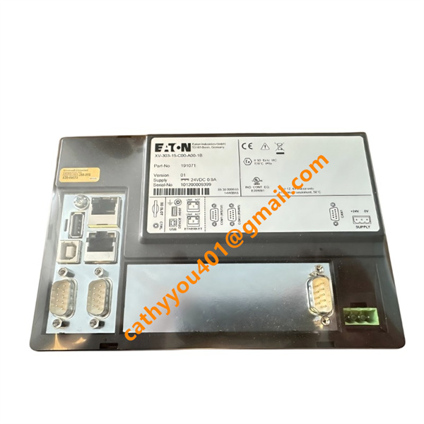






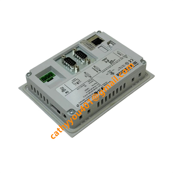
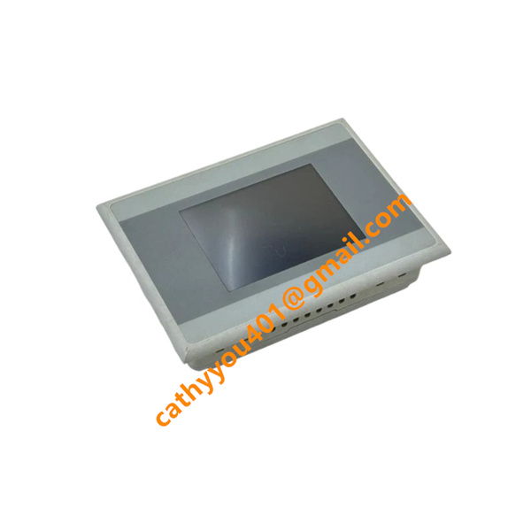







Description
-
BrandEATON
-
ModelXV-252-57MPN-1-10
-
Product NameIndustrial Heavy-Duty Hydraulic Cartridge Valve / Flow Control Valve
-
Country of OriginUnited States
-
HS Code8481201000
-
Dimensions85mm×60mm×45mm
-
Weight0.8kg
-
Operating Temperature-30°C to +80°C
-
Storage Temperature-40°C to +90°C
-
Power Supply24VDC
-
Warranty12 month
-
Product StatusNew and original
EATON XV-252-57MPN-1-10 Product Introduction and Technical Specifications
Input Technical Parameters
Hydraulic Pressure Input: Supports rated working pressure up to 35MPa, with instantaneous impact pressure resistance up to 42MPa. It adapts to high-pressure working conditions of industrial heavy-duty hydraulic systems and can withstand frequent pressure fluctuations and transient hydraulic impact.
Hydraulic Fluid Input: Applicable to standard industrial hydraulic oils, including mineral oil, anti-wear hydraulic oil and low-temperature hydraulic fluid. It supports normal fluid viscosity range of 10~400 cSt, meeting the fluid supply requirements of various industrial hydraulic systems.
Control Signal Input: Equipped with mechanical proportional control structure, supporting manual and hydraulic pilot signal input. It can receive remote hydraulic pilot control signals to realize stepless flow adjustment, with sensitive signal response and low control hysteresis.
Output Technical Parameters
Hydraulic Flow Output: Features precise adjustable flow output, with rated maximum flow capacity meeting standard industrial medium-flow hydraulic system requirements. It realizes stable stepless flow regulation, effectively ensuring uniform and stable operation speed of hydraulic cylinders and hydraulic motors.
Pressure Maintenance Output: With excellent pressure holding and pressure stabilization performance, it can maintain stable system output pressure during load changes, avoid equipment jitter and speed fluctuation, and improve the stability of hydraulic actuator operation.
Leakage Control Output: Adopts high-precision sealing structure, with extremely low internal leakage. It effectively reduces hydraulic system energy loss and ensures accurate flow control accuracy under long-term working conditions.
System Protection Output: Built-in flow limiting and overload buffer function, which can automatically limit excessive system flow and absorb hydraulic impact, realizing passive protection of hydraulic pipelines and actuators.

XV-252-57MPN-1-10 EATON Product Core Advantages
Superior Pressure Resistance and Stability: Made of high-strength alloy precision forging materials, the valve body has high structural rigidity and pressure resistance. It can operate stably under high-pressure and heavy-load working conditions for a long time, with no deformation or performance attenuation, ensuring long-term reliable operation of the hydraulic system.
High-Precision Flow Regulation: Adopts EATON’s mature fluid control structure and precision machining process, with extremely low regulation hysteresis and high flow control accuracy. It can realize stepless precise adjustment of hydraulic flow, effectively improving the motion precision and operation stability of hydraulic equipment.
Excellent Anti-Leakage and Energy-Saving Performance: Equipped with imported high-quality sealing components and optimized internal flow channel design, it minimizes internal and external leakage of the valve body, reduces hydraulic system energy consumption, and improves the overall energy utilization rate of mechanical equipment.

XV-252-57MPN-1-10 EATON Wiring and Installation Method
The EATON XV-252-57MPN-1-10 adopts standard cartridge embedded installation mode with standardized hydraulic port layout, featuring simple and orderly assembly process suitable for modular hydraulic manifold installation.
For hydraulic pipeline connection, clean the manifold valve cavity and pipeline impurities thoroughly before installation to avoid particle contamination affecting valve body performance. Embed the valve body into the standard cartridge valve cavity of the hydraulic manifold in a standardized direction, and tighten the fixing parts according to the specified torque to ensure tight and stable fitting without oil leakage.
For control loop connection, connect the main oil inlet pipeline to the valve body input port and the actuator oil pipeline to the output port according to the hydraulic system circuit design. For pilot control models, connect the pilot control oil circuit to the corresponding control port to complete the control signal loop layout.
After installation, conduct hydraulic pressure test and flow debugging. Gradually increase the system working pressure, check for pipeline oil leakage and abnormal valve body vibration, calibrate the flow regulation parameters to ensure stable and accurate flow output, and verify that the overall hydraulic system operates normally without jitter, stagnation and pressure fluctuation problems.