





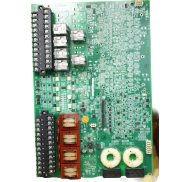







Description
-
BrandGE
-
ModelIS200ESYSH3A
-
Product NameExcitation Control System I/O Terminal Board
-
Place of OriginUnited States
-
Customs HS Code85371011
-
Power Supply0.7 A
-
Dimensions280mm × 170mm × 30mm
-
Weight1.25 kg
-
Operating Temperature-20°C ~ +70°C
-
Storage Temperature-40°C ~ +90°C
-
Warranty12 month
-
Product Statusnew
Operating Guide for GE IS200ESYSH3A
1. Pre-operation Safety & Inspection
Disconnect all cabinet power supplies and execute lockout-tagout procedures prior to any work. Perform visual inspection on the board to identify physical damage, burnt components or broken connectors. Check all screw terminal blocks for loose connections. Verify that the 55VDC power supply at terminal J13M1 complies with rated specifications. Confirm proper termination of CT/PT secondary wiring and ensure short-circuit protection is fitted for CT loops. Inspect the integrity of isolation transformers and D-Sub HSLA connectors. Confirm the board operates under simplex configuration and is not deployed for redundant control circuits.
2. Hardware Installation
Install the IS200ESYSH3A into its designated slot within the EX2100e exciter cabinet and fasten the board mounting screws. Fit HSLA daughter cards into the 6 D-Sub ports on the board. Complete field wiring to terminal blocks: connect 2 sets of generator CT inputs (selectable 1A/5A), 2 sets of 3-phase PT inputs, 7 channels of 55VDC auxiliary contact inputs, and 2 Form-C trip relay outputs. Route high-power CT/PT cables separately from low-voltage signal wires to mitigate electromagnetic interference. Implement appropriate cable shielding and grounding. Double-check CT wiring to eliminate the risk of dangerous open-circuit conditions on CT secondary circuits.
3. System Configuration via ToolboxST
Open GE ToolboxST engineering software and load the target EX2100e project. Add the IS200ESYSH3A to the hardware tree and select the correct board revision. Configure CT/PT transformer ratios, signal scaling parameters and auxiliary contact input logic. Define trip relay operating logic and interlock conditions in accordance with generator protection requirements. Set HSLA high-speed serial communication parameters between the terminal board and M1 controller. Compile the project and download hardware configuration together with excitation control logic to the EX2100e main controller.
4. Power-on and Initial Board Check
Energize the exciter cabinet and 55VDC power supply. Observe the front panel status LEDs; the corresponding LED will illuminate when an auxiliary contact input is closed. Switch to online mode in ToolboxST to confirm the controller recognizes the IS200ESYSH3A. Check board health, communication status and signal quality in the diagnostic menu. Resolve any HSLA communication failures, power supply anomalies or channel mismatches before proceeding with subsequent tests.
5. Channel Loop Test
Conduct point-to-point loop testing for every channel. Inject simulated current signals into CT inputs and validate measured readings within ToolboxST. Apply three-phase voltage to PT inputs and verify voltage feedback values. Toggle auxiliary contact inputs and confirm correct status indication. Activate trip relay outputs and verify contact actuation at field terminals. Confirm the built-in isolation protection functions as expected. Document all test results for commissioning records.
6. Excitation System Functional Test
Run offline simulation first to validate voltage regulation and protection logic. Carry out online functional tests covering excitation control, overvoltage protection, loss-of-field protection and generator trip interlocks. Simulate abnormal process conditions to verify trip relays operate as designed. Confirm the response time of excitation regulation and protection actions meets generator control specifications. Correct any signal deviation or logic inconsistency.
7. Normal Online Operation & Monitoring
During normal generator operation, monitor CT/PT measured values, auxiliary contact status and trip relay states via ToolboxST or the plant HMI. The board continuously transmits field I/O data to the EX2100e controller over the HSLA link. Keep watch for diagnostic alarms related to wiring faults, power supply drift or communication loss. Hot-swap is prohibited during live operation since this is simplex hardware without redundancy.
8. Maintenance & Fault Handling
Upon fault occurrence, retrieve fault codes and diagnostic data from ToolboxST. Inspect terminal wiring, 55VDC power supply, HSLA daughter card and connectors. If the board is confirmed defective, shut down the relevant excitation section before replacement. After installing the new board, reload configuration and repeat point-to-point testing before restoring system operation. Maintain a clean cabinet environment and protect the board from dust, high humidity and excessive vibration.

GE IS200ESYSH3A Detailed Specifications
Basic Information
Applicable System: GE EX2100e generator excitation control system
Functional Definition: ESYS (Excitation System I/O Interface), serving as the dedicated field signal acquisition and output terminal board for excitation systems
Redundancy Configuration: Simplex single-channel structure (non-redundant, no online fault tolerance)
Official Reference Manuals: GEI-100772, GEH-6784D, GEH-6781L
Input & Output Signals
Analog Measurement Inputs
Generator CT Input: 2 groups of current transformer sampling inputs, supporting switchable 1A/5A rated current; equipped with onboard independent isolation transformers to achieve complete galvanic isolation
Generator PT Input: 2 groups of three-phase voltage transformer sampling inputs, integrated with dedicated isolation transformers for anti-interference isolation processing
Digital Inputs
Auxiliary Contact Inputs: 7-channel digital contact inputs, adopting 55VDC wetting power supplied via the J13M1 terminal; each channel is equipped with a dedicated status LED indicator, which lights up when the field contact closes
Relay Outputs
Trip Relay Outputs: 2-channel standard Form-C programmable trip relay contacts (K1, K2), with a rated driving coil voltage of 125VDC
Extended General Relay Outputs (partial board revisions): 4-channel Form-C auxiliary relay outputs (K1GP–K4GP) for expanded interlock control
Power Supply Specifications
Working Power Supply: 55VDC working power, supplied by the EX2100e M1 power module through the J13M1 dedicated connector
Power Supply Standard: Fully compliant with the 55VDC power rail technical specifications of the EX2100e excitation cabinet rack
Communication Interface
Hardware Interface: 6 onboard D-Sub interfaces, compatible with HSLA/EMIO high-speed serial daughter cards
Communication Protocol: HSLA high-speed serial link (HSSL)
Communication Function: Realizes high-speed, stable data interaction and signal transmission between the terminal board and EX2100e M1 main controller
Terminal & Wiring Specifications
Terminal Type: Screw-type barrier terminal blocks, supporting reliable field wiring fixation
Applicable Wire Gauge: #12 AWG to #24 AWG
Signal Processing: Built-in professional signal conditioning circuits; all CT and PT measurement channels adopt independent isolation transformers to eliminate ground loop interference
Environmental Specifications
Operating Temperature Range: -40℃ ~ +85℃, adapting to harsh industrial on-site environments
Relative Humidity: Up to 95% non-condensing humidity
Installation Mode: Standard chassis plug-in installation, fixed inside the EX2100e excitation control cabinet
Hardware & Diagnostic Characteristics
Status Indication: Equipped with front-panel LED indicators, real-time displaying board operating status and digital input channel states
Isolation Performance: Full galvanic isolation design for CT/PT measurement loops, effectively suppressing on-site electromagnetic noise and ground interference
Comprehensive Diagnosis: Supports real-time monitoring of channel status, communication link health and power supply operating conditions
Hot-Swap Function: Not supported. The board belongs to simplex non-redundant hardware, requiring full power-off operation for replacement and maintenance, and online hot replacement is prohibited

DS200TDAH1BHD
DS200TCRAG1ACC
DS200DTRAG1AAA
DS200DTBBG1ABB
DS200SDCCG4AFD
DS200TCDAG1BDB
IS220PTURH1B
C60G01HCHF8FH6PM8FP6PU6PWXX
DS200TCQCG1BHF



.jpg)







