.jpg)
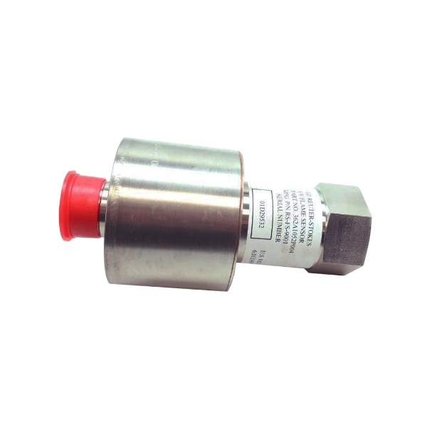







Description
-
BrandGE
-
ModelRS-FS9001 362A1052P404
-
Product NameFlame Tracker UV Flame Detector
-
Place of OriginUnited States
-
Customs HS Code90271000
-
Power Supply12V DC to 30V DC
-
Dimensions114mm × 76mm × 51mm
-
Weight0.22kg
-
Operating Temperature-40°C to +150°C
-
Storage Temperature-40°C to +70°C
-
Warranty1 year
-
Product Statusnew
Commissioning Procedure for GE RS-FS9001 (362A1052P404) UV Flame Detector
Pre-commissioning Inspection
Examine the probe and amplifier assembly for mechanical damage. Ensure the UV lens is free of scratches and the MIL 5-pin connector remains intact. Confirm the 3/4 NPT mounting thread fits the burner sight port. Assess the cabinet environment to prevent exposure to direct sunlight, arc light and hot soot contamination. Prepare a 24 VDC regulated power supply, multimeter, 4–20 mA calibrator, UV test lamp and BMS maintenance tools. Isolate the fuel supply and implement lockout/tagout for the combustion system prior to any work.
Mechanical Installation and Sight Alignment
Install the detector onto the burner sight port with a suitable gasket to prevent gas leakage. Adjust the probe angle so its optical axis targets the primary flame zone, and avoid aiming at hot refractory surfaces. Maintain lens cleanliness and refrain from touching the UV window directly by hand. Tighten fittings in accordance with GE specifications without imposing mechanical stress on the probe cable. Route cables away from high-temperature piping and high-current power cables.
Wiring and Continuity Check (Power Disconnected)
Complete wiring following the pin assignment, including 24 VDC power, 4–20 mA analog output and fault relay contacts. Measure cable insulation resistance and ensure no short circuits exist between power and signal conductors. Terminate the cable shield only at the amplifier end and avoid dual-point grounding. Verify wiring consistency with the BMS flame input card.
Static Power-up and Self-diagnosis
Apply 12–30 VDC auxiliary power with 24 VDC as the nominal rating. Monitor the power LED and self-test sequence. The normal quiescent output with no flame is approximately 4 mA. If a fault code is triggered, inspect supply voltage, connector contacts, lens contamination or internal sensor failure.
Bench UV Lamp Simulation Test (No Combustion)
Irradiate the detector window using a calibrated UV test lamp. Measure the current output; the reading should rise to 12–20 mA under valid UV excitation. Confirm the BMS receives the flame-present signal and the fault relay resets accordingly. Remove the UV source. The output shall fall back to around 4 mA, and the BMS shall register flame loss within the specified response time. Adjust the BMS flame threshold as required.
On-site Cold Check with Burner System
Keep the fuel valve closed and operate burner fans for purging. Confirm the detector baseline signal remains low and stable, free from false flame signals induced by stray UV from the spark igniter. Test the BMS flame-loss trip logic to validate the shutdown sequence.
Hot Commissioning with Actual Flame
Initiate ignition after completing standard purging sequences. Track the 4–20 mA signal during ignition and steady combustion. Record flame signal strength under low-fire and high-fire conditions. Verify rapid flame-out detection and fuel cutoff commanded by the BMS. Watch for signal fluctuations caused by soot buildup or misalignment, and recalibrate the sight angle if readings deteriorate.
Sensitivity and Fault Function Test
Simulate fault conditions including power loss, open circuits and lens obstruction. Confirm the detector enters the fault state, outputs the fault current level and energizes the fault relay. Validate BMS fault alarms and voting logic. Ensure the detector operating temperature never exceeds its maximum ambient rating.
Post-commissioning Documentation and Handover
Document the 4 mA baseline (no flame) and flame-activated current values, fault test results and final sight alignment position. Clean the UV lens and recheck all cable glands and sealing points. Back up the BMS configuration and event logs.

Common Troubles During GE RS-FS9001 (362A1052P404) Commissioning
Possible causes: 24 VDC power supply out of rated range, reversed power polarity, loose or corroded 5-pin MIL connector, broken internal cable core.
Symptom: Power LED remains unlit, with no valid 4–20 mA signal output.
Persistent Fault Alarm with Fixed Fault Current Output
Possible causes: UV lens severely contaminated by soot, dust or oil stains; aging UV sensor; internal amplifier circuit failure; cable open circuit; ambient temperature exceeding the maximum operating specification.
Symptom: The detector is locked in fault state and cannot complete reset recovery.
False Flame Signal (Flame Present Without Actual Combustion)
Possible causes: Detector optical axis facing hot refractory surfaces; stray UV interference from ignition sparks, welding arcs or direct sunlight; reflected ultraviolet light; severe EMI coupling on signal cables.
Symptom: 4–20 mA signal rises abnormally, and BMS mistakenly judges flame existence during unit purging or standby status.
No Valid Flame Signal After Burner Ignition
Possible causes: Incorrect probe alignment with optical axis deviating from the main flame zone; lens covered with soot; dense smoke absorbing UV light; burner structural obstruction; weak UV radiation generated by combustion flame.
Symptom: The detector output stays around 4 mA even after successful burner ignition.
Unstable and Fluctuating 4–20 mA Flame Signal
Possible causes: Poor connector contact; signal cables laid in parallel with high-power cables causing strong EMI interference; intermittent soot accumulation on the lens; unstable flame pulsation; loose detector mounting threads.
Symptom: Real-time flame signal fluctuates drastically, triggering sporadic flame loss alarms.
Slow Flame Loss Response
Possible causes: Unreasonable BMS flame threshold and delay parameter settings; partially blocked UV lens leading to reduced detection sensitivity.
Symptom: The actual flame has extinguished, but the BMS system delays fuel cutoff trip action.
4–20 mA Output Out of Normal Range
Possible causes: Mismatched load resistance of BMS analog input card; damaged amplifier output circuit; ground loop interference caused by double-end shield grounding.
Symptom: Current output fails to reach standard full-scale value or suffers continuous signal drift.
Abnormal Fault Relay Contact
Possible causes: Burned relay contacts; incorrect fault relay wiring; mismatch between relay contact rating and BMS input specifications.
Symptom: System fails to report faults normally, or the fault signal keeps latched even after the fault is eliminated.
Normal Bench Test but On-Site Detection Failure
Possible causes: Deviation between UV spectrum of test lamp and actual combustion flame; on-site smoke, steam or fuel characteristics weaken UV radiation; optical path blocked under high-temperature operating conditions.
Symptom: The detector passes laboratory UV simulation test but works abnormally in actual combustion scenarios.
Lens Fogging and Rapid Re-Contamination
Possible causes: Poor sealing of mounting gasket; high-temperature gas leakage from burner sight port; excessive internal humidity of probe assembly.
Symptom: Detection signal attenuates rapidly soon after lens cleaning.

DS200TDAH1BHD
DS200TCRAG1ACC
DS200DTRAG1AAA
DS200DTBBG1ABB
DS200SDCCG4AFD
DS200TCDAG1BDB
IS220PTURH1B
C60G01HCHF8FH6PM8FP6PU6PWXX
DS200TCQCG1BHF



.jpg)