





.jpg)
.jpg)
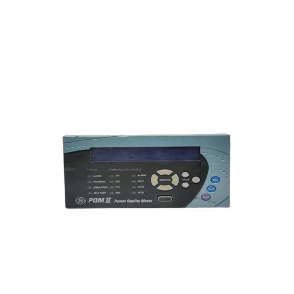







Description
-
BrandGE
-
ModelPQMII-T20
-
Product NamePQMII Digital Power Quality Meter with Transducer Output Option
-
Place of OriginCanada
-
Customs HS Code90283090
-
Power Supply70‑265 VAC or 90‑300 VDC
-
Dimensions144 mm × 192 mm × 103 mm
-
Weight2.7 kg
-
Operating Temperature‑10 °C to +60 °C
-
Storage Temperature‑20 °C to +70 °C
-
Warranty12 month
-
Product Statusoriginal
GE Multilin PQMII-T20
Inputs
1. AC Voltage Measurement Input (V1,V2,V3,Vn)
Line-to-line input voltage range: 20-600 VAC. It supports direct connection or connection through external voltage transformers (VT). Burden consumption is less than 0.1 VA and measurement adopts True-RMS algorithm.
2. AC Current Measurement Input (Ia,Ib,Ic,In)
Compatible with 1 A or 5 A CT secondary signals. Burden ranges from 0.1 VA to 0.2 VA. Short-term overload capacity: 100×CT for 0.2 seconds, 20×CT for 1 second.
3. Control Power Supply Input
Accepts 70-265 VAC (50/60 Hz) or 90-300 VDC auxiliary power. Nominal power consumption is 10 VA with maximum value of 20 VA. Typical power hold-up time reaches 100 ms under 120 VAC/VDC condition.
4. Digital Status Input (Dry-contact DI)
Dry-contact input type. Pick-up current is 2 mA at 24 VDC. Maximum allowed on-state contact resistance is 1000 Ω. Minimum recognizable pulse duration is 100 ms.
5. Pulse Input
Provides up to 4 pulse input channels for energy pulse accumulation. Minimum detectable pulse width is 15 ms.
Outputs (T20 variant)
1. Analog Output (AO, T20 option)
Isolated 4-20 mA active-source analog output. Maximum load resistance is 600 Ω and peak output current is 21 mA. Dielectric isolation rating: 50 V.
2. Form-C Relay Outputs
Contact ratings: 5 A @250 VAC resistive load, 5 A @30 VDC resistive load; 5 A @250 VAC inductive load (PF=0.4). Functions are programmable for alarm triggering, local control, load shedding and energy pulse output.
Communication Interfaces
COM1 / COM2: Galvanically isolated two-wire half-duplex RS485 interface; baud rate range:1200-19200 bps.
COM3: Front-mounted 9-pin RS232 service port; baud rate range:1200-19200 bps.
Ethernet communication can be expanded via optional Multi-Net module.

Supported Protocols
Modbus-RTU (RS485/RS232): used for parameter read-write, real-time value acquisition and event retrieval.
DNP3.0 Level 2: dedicated for SCADA data acquisition and event reporting.
Modbus-TCP is available when the optional Multi-Net module is installed.
Supported Software
EnerVista PQMII Setup Software: completes parameter configuration, waveform downloading, power-quality event analysis and historical log browsing.
Third-party SCADA and DCS platforms: GE Cimplicity, Wonderware, Siemens WinCC, ABB 800xA and other HMI systems, communicating through Modbus-RTU or DNP3.0 protocols.
Compatible Systems
Industrial SCADA systems, plant-wide DCS, substation automation systems, power-quality monitoring platforms, energy management EMS and building energy monitoring systems.
Measurement capability
Measures three-phase voltage and current, active/reactive/apparent power, power factor, demand and energy values. Supports harmonic calculation up to 63rd-order and total harmonic distortion (THD). It can record voltage sag, swell and power interruption events, capture transient waveforms and store disturbance logs with time stamps.

Working Principle of GE Multilin PQMII-T20 Power Quality Meter
The PQMII-T20 is a multifunctional instrument for power-quality monitoring and energy metering. It samples voltage and current signals from VT and CT secondary loops, carries out high-speed digital computation, captures power-system disturbance events, and delivers data via various communication ports.
1. Signal Acquisition
Three-phase voltage (V1, V2, V3) and three-phase current (Ia, Ib, Ic) are retrieved from the secondary windings of voltage transformers (VT) and current transformers (CT). The unit supports 1 A or 5 A CT secondary current, as well as direct-input line-to-line voltage ranging from 20-600 VAC. Dry-contact digital inputs and pulse inputs acquire external status feedback and energy pulse signals respectively. All incoming analog signals go through galvanic isolation and signal conditioning before being fed to the high-speed ADC module.
2. High-speed Sampling and ADC Conversion
The built-in analog-to-digital converter continuously samples instantaneous voltage and current waveforms. Collected analog quantities are converted into digital datasets for the main microprocessor. True-RMS computation is implemented to guarantee accurate measurement even for distorted waveforms rich in harmonic components.
3. Digital Calculation and Power-Quality Analysis
The main microcontroller performs real-time arithmetic processing over sampled raw data:
Fundamental electrical quantities: RMS voltage, RMS current, active power, reactive power, apparent power, power factor, frequency, demand values and accumulated energy.
Harmonic analysis: computes harmonic components up to the 63rd-order together with total harmonic distortion (THD).
Disturbance identification: keeps tracking voltage sags, swells and supply interruptions. Once measurement results exceed user-defined thresholds, waveform capture is activated, and time-stamped disturbance records are saved.
4. Logic Processing and Output Control
Threshold parameters are configured through the EnerVista software. When process variables breach alarm setpoints, the instrument actuates programmable Form-C relay outputs to implement alarm notification or load-shedding actions. The optional 4-20 mA analog outputs convert selected measurement variables into isolated current signals for interfacing with DCS systems or chart recorders.
5. Event and Data Storage
Measured values, cumulative energy data, captured disturbance waveforms and fault event logs are stored within non-volatile memory. Time-synchronization mechanisms ensure precise timestamps for every logged incident, and stored data remains intact upon auxiliary power failure.
6. Communication-based Data Exchange
Real-time measurements, historical logs and waveform files are uploaded by the processor through hardware interfaces: RS485 (Modbus-RTU, DNP3.0), front-panel RS232, or optional Ethernet with Modbus-TCP. The device interacts with EnerVista configuration tool, SCADA platforms, EMS and substation automation systems.
7. Internal Power-supply Circuit
The onboard power unit accepts 70-265 VAC or 90-300 VDC auxiliary supply, and generates regulated internal power for signal-acquisition circuits, microprocessor, memory and communication peripherals.

DS200TDAH1BHD
DS200TCRAG1ACC
DS200DTRAG1AAA
DS200DTBBG1ABB
DS200SDCCG4AFD
DS200TCDAG1BDB
IS220PTURH1B
C60G01HCHF8FH6PM8FP6PU6PWXX
DS200TCQCG1BHF



.jpg)
.jpg)







