





7B132D98A103472DBE72EC313B771FA7.jpg)
.jpg)
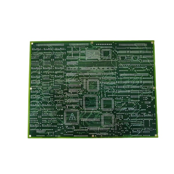







Description
-
BrandGE
-
ModelDS200TCCBG3B
-
Product NameCommon Extended Analog I/O Board (TC2000)
-
Place of OriginUnited States
-
Customs HS Code8538900000
-
Power Supply5 VDC logic power and ±15 VDC analog power
-
Dimensions203 mm × 127 mm × 40 mm
-
Weight0.5 kg
-
Operating Temperature0℃ to +60℃
-
Storage Temperature‑40℃ to +85℃
-
Warranty1year
-
Product Statusnew
GE DS200TCCBG3B Characteristics
Product Type: General extended analog I/O board designed for the GE Speedtronic Mark V turbine control system
Core Processor: Integrated Intel 80196 microprocessor with multiple on-board PROM modules for firmware storage and local logic operation
Main Function: Performs conditioning, filtering, scaling and acquisition of field analog signals for gas and steam turbine control systems; supports collection of generator voltage, bus voltage, line current, RTD temperature, 4–20 mA and 0–1 mA analog signals
Connectors: Equipped with two 50-pin external signal connectors (JCC, JDD) for field wiring and multiple auxiliary internal connectors for inter-board data and power interconnection
Hardware Configuration: Configurable on-board jumpers for hardware parameter setup, including generator/bus voltage range, current monitoring parameters and RS232 serial test port activation
Status Indicator: Single green operation LED for real-time board status indication; steady ON status represents normal power supply and running state, while OFF status indicates power failure or hardware abnormality
Power Supply: Powered by the system TCPS power module, providing stable +5 VDC for digital logic circuits and ±15 VDC for analog signal circuits
Operating Temperature: Rated continuous operating temperature range from 0 °C to +60 °C for standard cabinet installation
Diagnostic Feature: Fully compatible with native Mark V system drive diagnostics; supports fault code recording and abnormal event uploading via serial interface for convenient troubleshooting and maintenance
Physical Form: Standard Eurocard-style PCB, applicable for slot-type installation in the Mark V R5 core chassis
Compatibility: Exclusive hardware for Mark V turbine control system, realizing data interaction and logic coordination with TBCB and TCEB internal boards; incompatible with Mark VIe system without hardware modification

Detailed Hardware Configuration of GE DS200TCCBG3B (TCCB Common Extended Analog I/O Board, Mark-V Speedtronic)
1. Core Processing and Memory Unit
Main Microprocessor: Equipped with Intel 80196 16-bit microcontroller integrating a watchdog timer and 8 KB on-chip ROM. It undertakes analog signal scaling, data conversion, board self-diagnosis and internal bus data communication.
Firmware Storage: Adopts socket-type PROM chips for independent firmware storage, supporting individual PROM replacement for version upgrades without changing the entire PCB.
On-board Peripheral Logic: Consists of discrete logic chips, operational amplifiers, filter circuits and sampling circuits, realizing multi-type field analog signal conditioning and processing.
2. Power Supply Circuit
The board is powered exclusively by the Mark-V R5 rack internal TCPS power board without external power supply.
Logic Power: +5 VDC, serving the microprocessor and all digital logic circuits.
Analog Power: ±15 VDC, dedicated to operational amplifiers and analog signal conditioning circuits.
Power Filtering System: Equipped with multiple electrolytic and ceramic capacitors to suppress backplane power noise and ensure stable board operation.
3. Connector Layout
All onboard connectors are categorized as field signal interfaces and internal inter-board interfaces:
JCC, JDD (50-pin female connectors): Primary field signal ports for receiving generator/bus voltage, line current, RTD temperature, 4–20 mA and 0–1 mA analog input signals.
2PL Connector: Internal power interface for power input from the TCPS module.
3PL Connector: Inter-board data bus for transmitting processed analog data to STCA and TCCA boards.
JHH, JII, JMP: Auxiliary interconnection connectors for signal interaction with R5-core TBCB and P1-core TCEB boards.
JKK, JTEST, TCQPL: Reserved test connectors, unused during normal system operation.

4. Hardware Jumper Configuration (J1-J5, J14-J16)
All jumpers adopt pin-header design with removable short caps for hardware parameter configuration, which cannot be modified by software.
J1–J5: Configure generator and bus voltage measurement ranges, as well as line current monitoring parameters to match on-site PT/CT transformation ratios.
J14: Enables the onboard RS-232 serial test port when shorted, supporting local device diagnosis and data reading.
J15, J16: Factory-reserved test jumpers. Must remain factory default status in field operation to avoid hardware abnormalities.
5. Status Indication and Diagnostic Hardware
A single front-mounted green LED provides real-time operating status indication:
LED ON: Normal power supply and stable microprocessor operation.
LED OFF: Power failure, processor shutdown or critical hardware fault.
The integrated hardware diagnostic circuit cooperates with the native Mark-V system diagnosis function. Fault codes, over-range signals and hardware failure records can be retrieved via the RS-232 port or system HMI for troubleshooting.
6. Analog Signal Conditioning Circuit
Multi-channel operational amplifier circuits perform unified attenuation, amplification, filtering and level conversion for diverse analog inputs.
It is compatible with AC voltage, AC current, RTD resistance and DC milliamp signals. Built-in anti-aliasing filters eliminate high-frequency noise and ensure accurate ADC sampling results.
7. Physical and Mechanical Structure
Form Factor: Standard Eurocard PCB designed for plug-in installation in Mark-V R5 core rack slots.
Installation Method: Fixed by rack guide rails and electrically connected to the backplane via edge gold-finger contacts.
Operating Environment: Rated continuous operating temperature of 0 °C to +60 °C, suitable for indoor turbine cabinet installation, not for direct outdoor field exposure.

DS200TDAH1BHD
DS200TCRAG1ACC
DS200DTRAG1AAA
DS200DTBBG1ABB
DS200SDCCG4AFD
DS200TCDAG1BDB
IS220PTURH1B
C60G01HCHF8FH6PM8FP6PU6PWXX
DS200TCQCG1BHF


.jpg)

.jpg)
.jpg)







