




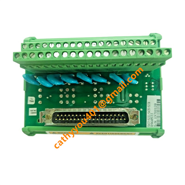
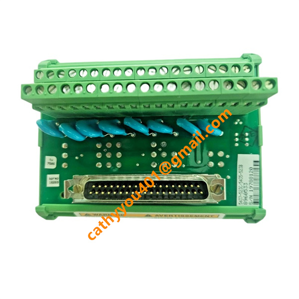
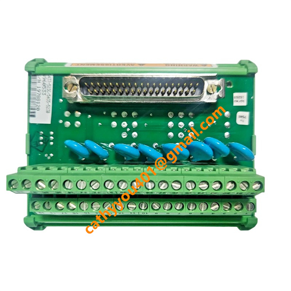







Description
-
BrandWoodward
-
Model5437-523
-
Product NameDigital Governor Control Card
-
Place of OriginUnited States
-
HS Code9032899099
-
Dimensions345mm×170mm×42mm
-
Weight0.9 kg
-
Operating Temperature-40°C to +75°C
-
Storage Temperature-45°C to +85°C
-
Power Supply24vdc
-
Warranty12 month
-
Product StatusNew and original
Woodward 5437-523 Input & Output
Power Input: Dual redundant 18–36 VDC, typical 24 VDC; rated power consumption 72W
Analog Inputs: 8 isolated channels, supports -10~+10VDC / 4–20mA sensor signals
Speed Inputs: 2 independent magnetic pickup channels, frequency range 5Hz–20000Hz
Analog Outputs: 4 isolated channels (0–10V / 4–20mA) for proportional actuators
Servo Drive Outputs: 4 groups ±100mA driver outputs for fuel control valves
Communication Interfaces: Dual CAN 2.0 bus + RS485 Modbus RTU digital I/O bus
Status Output: Front panel LED indicators for power, operation, communication and fault alarms
Backplane I/O: Multi-row rear pin connector for inter-board power and signal transmission
Mounting Method of Woodward 5437-523
Rack Card Installation Structure
It is a standard pluggable rack board intended for vertical mounting in dedicated Woodward control cabinets with matching backplane slots. Standalone installation without a supporting rack is not supported.
Insertion & Locking Steps
Align the multi-pin rear connector with the cabinet backplane socket and push the board completely into the slot. Fasten the metal ejector latches on both sides to guarantee stable electrical contact, then secure the front panel mounting screws for vibration resistance.
Clearance & Heat Dissipation Rules
Maintain a minimum 30mm gap above and below the board for natural cooling. Do not place heat-emitting modules next to it, and keep all cabinet ventilation openings unobstructed.
Wiring & Grounding Requirements
Power, speed feedback and analog signals are routed through the rear backplane to matching terminal modules. Separate power cables from signal wiring. Firmly link the cabinet protective earth to the board’s grounding terminal to reduce electromagnetic interference.
Environmental Installation Restrictions
Indoor installation only, with a working ambient temperature of -40°C to +75°C. Avoid locations with high heat, moisture, dust, corrosive fumes or sustained severe mechanical vibration.
Maintenance Reminders
Cut off the cabinet main power before plugging or unplugging the board to avoid pin and signal circuit damage. The front debug header is solely for temporary commissioning wiring.