





.jpg)
F49C84D4CC084148A313D9D2AE267B51.jpg)
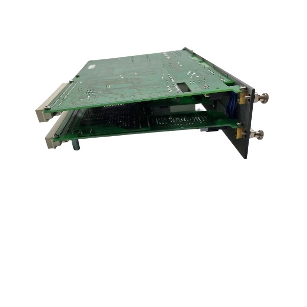







Description
-
BrandDEIF
-
ModelSCM 4.2 2044220100 K
-
Product NameSynchronisation and Control Module
-
Place of OriginDenmark
-
Customs HS Code85389000
-
Power Supply210mA
-
Dimensions233mm × 128mm × 24mm
-
Weight0.41kg
-
Operating Temperature-25°C to +70°C
-
Storage Temperature0°C Storage Temperature:
-
Warranty12 month
-
Product Statusnew
Wiring Method for DEIF SCM 4.2 (2044220100 K)
Rack Backplane Bus Connection
Insert the module into a standard Delomatic 4 rack. The internal backplane bus realizes power supply and data interaction with PCM4.2/PCM4.1 master control modules. The dedicated 8-core internal connecting cable between the AC measurement board and EM engine control board must be kept intact and properly connected.
AC Voltage Measurement Wiring
Support direct AC voltage measurement up to 690 VAC. Connect generator terminal voltage signals to GEN L1/L2/L3/N terminals, and switchboard busbar voltage signals to BUS L1/L2/L3/N terminals for synchronization, voltage monitoring and power calculation. Use dedicated insulated voltage cables, and install independent fuses on all voltage input phases for circuit protection.
Current Transformer (CT) Wiring
Connect 1 A or 5 A CT secondary signals to the corresponding S1/S2 phase current input terminals. The CT secondary side requires single-point grounding, and open-circuit operation of the CT secondary is strictly forbidden during operation. Complete CT ratio parameter matching via DEIF Smart Connect configuration software after wiring.
Auxiliary Power Supply Wiring
The module adopts 24 VDC power supply, connected to +24 V and 0 V terminals. Use shielded twisted-pair cables for power wiring. The power source shall be supplied by the system PCM module or an isolated 24 VDC power unit. Do not share the power loop with high-current execution actuators to avoid interference.
Binary Digital Input Wiring
All digital inputs adopt passive potential-free dry contact mode, covering engine emergency stop, operation state feedback, circuit breaker position feedback and equipment fault signals. All dry contact inputs share the public DI common terminal for unified signal acquisition.
Relay Binary Output Wiring
Potential-free relay outputs are used for circuit breaker closing/tripping control, as well as binary switching control of governors and AVRs. External power supply shall be configured according to the rated parameters of field actuator coils. The optional OPR-1 relay sub-board is exclusively applicable to mechanical governors and mechanical AVRs.
Analogue Control Output Wiring
Provide ±20 mA analogue signals for speed governor and AVR regulation. Adopt shielded twisted-pair cables with single-point shielding grounding at the module side. Install external conversion resistors if the governor requires voltage control signals.
Engine Analogue Sensor Input Wiring
Support multi-type sensor access: 2-wire/3-wire/4-wire Pt100/Pt1000 temperature sensors, K-type thermocouples for exhaust temperature monitoring, and 4–20 mA analogue transmitters for pressure and liquid level signal collection.
CAN Bus Communication Wiring
Shielded twisted-pair cables are used for engine ECU CAN bus communication, with a baud rate range of 125–1000 kbps. Install termination resistors at both ends of the CAN network. Keep CAN communication cables separated from high-power power cables to prevent signal interference.
Shielding and EMC Requirements
All low-level signal cables must use shielded twisted pairs, with shields grounded only at the SCM4.2 module end. Classify and lay high-voltage AC measurement cables, power cables and weak-current sensor cables in separate cable trays to eliminate cross electromagnetic interference.

AC Voltage Measurement Wiring for DEIF SCM 4.2 (2044220100 K)
1. Overview of AC Voltage Input
The SCM 4.2 is equipped with two independent voltage measurement channels for generator (GEN) and busbar/mains (BUS) voltage respectively. These channels support synchronisation, voltage supervision, overvoltage and undervoltage protection, as well as power calculation. The module can accept AC inputs up to 690 VAC at 50 Hz or 60 Hz, and the voltage inputs feature internal galvanic isolation.
2. Terminal Definition
Generator voltage terminals: GEN-L1, GEN-L2, GEN-L3, GEN-N
Busbar/mains voltage terminals: BUS-L1, BUS-L2, BUS-L3, BUS-N
For 3-phase 4-wire systems, all four terminals (L1/L2/L3 plus neutral N) shall be connected. For 3-phase 3-wire systems without a neutral conductor, leave the N terminal open and unconnected.

3. Wiring Connection Methods
3.1 Direct voltage connection (low-voltage generator or busbar, ≤690 VAC)
De-energise all high-voltage circuits and execute lockout-tagout procedures before commencing wiring work.
Run insulated single-core voltage cables from the generator terminals to GEN-L1, GEN-L2, GEN-L3 and GEN-N.
Run insulated single-core voltage cables from the switchboard busbar to BUS-L1, BUS-L2, BUS-L3 and BUS-N.
Fit separate miniature fuses on each phase upstream of the SCM 4.2 terminals. The recommended fuse rating ranges from 2 A to 6 A with gG characteristic.
Do not share the same set of voltage fuses between generator and busbar measurement loops.
3.2 Voltage transformer (VT) connection (for system voltages above 690 VAC)
Wire the secondary windings of the voltage transformers to the voltage terminals of the SCM 4.2.
Configure the VT secondary voltage (typically 100 VAC or 110 VAC line-to-line) in DEIF Smart Connect software to match the actual hardware.
The VT secondary circuit must be earthed in compliance with local electrical regulations.
Install fuses on each phase of the VT secondary; short-circuiting of VT secondary windings is strictly prohibited.
4. Cable Requirements
Use insulated copper cables rated for the system operating voltage.
Separate voltage measurement cables from high-current power cables and relay output cables to mitigate electromagnetic interference.
Avoid long runs of unshielded voltage cables routed in parallel with power cables.
If shielding is applied, the cable shield shall be earthed at only one point, generally at the switchboard side rather than the SCM module terminals.
5. Phase Sequence Check
The correct L1-L2-L3 phase sequence must be maintained for both generator and busbar voltage inputs. Incorrect phase sequence will lead to synchronisation failure and inaccurate power measurement.
After wiring and prior to commissioning, verify the phase sequence and voltage balance using a multimeter or phase indicator.
6. Parameter Configuration After Wiring
Launch DEIF Smart Connect software and configure the following settings:
System type: 3P4W or 3P3W
Rated voltage
VT ratio (when voltage transformers are used)
Nominal frequency: 50 Hz or 60 Hz
7. Critical Safety Rules
Voltage terminals carry live potential; all wiring operations must be completed with the circuits de-energised.
Fuses are required for voltage input protection to restrict fault current in the event of short circuits on measurement wiring.
Do not apply voltages exceeding the maximum 690 VAC rating directly to the module terminals.
If a neutral conductor is not available, keep the N terminal open. Do not jumper N to any phase conductor or protective earth.
The voltage terminals of the SCM 4.2 must never be used as a power source for other external devices.







