












Description
-
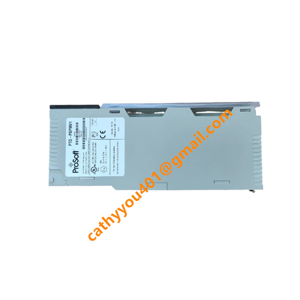
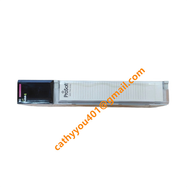
BrandProSoft
-
ModelPTQ-PDPS
-
Product NamePROFIBUS DP Slave Communication Module for Quantum PLC
-
Place of OriginUnited States
-
HS Code8542319000
-
Dimensions120 mm × 95 mm × 25 mm
-
Weight0.35 kg
-
Operating Temperature0 °C to +60 °C
-
Storage Temperature-40 °C to +85 °C
-
Power Supply24VDC
-
Warranty12 month
-
Product StatusNew and original

ProSoft PTQ-PDPS Wiring Method
1. Power Wiring
This PTQ-PDPS module does not need any external power wiring. After inserting the module into the Quantum PLC rack slot, it is powered directly by the PLC backplane automatically, with no extra DC power wires or terminals required.
2. PROFIBUS DP Bus Wiring (DB9 Interface)
The module adopts a standard DB9 port for PROFIBUS DP communication via RS-485 signals.
Pin 3: PROFIBUS Data + (Green wire)
Pin 8: PROFIBUS Data – (Red wire)
Pin 5: Signal ground

Use standard shielded twisted-pair PROFIBUS cable. Only ground the cable shield at one single end to prevent ground loop interference.
3. Bus Termination Setting
If this module is installed at the end point of the PROFIBUS network line, turn on the built-in 220 Ω terminal resistor. If it is installed in the middle of the network, keep the termination function off to prevent signal distortion and network instability.
4. Configuration Port Wiring
The module has a dedicated serial debug port. Connect this port to a computer with the special matching cable for parameter setup, network debugging, real-time status checking and fault troubleshooting. This port is only for commissioning use and does not work for normal running data communication.
5. Wiring Notes
Arrange PROFIBUS cables neatly. Avoid sharp bends, crossing with high-power cables and areas with strong electromagnetic interference. Ensure solid and reliable shield grounding. Never plug or unplug bus cables while the system is running, which will cause communication dropout and signal failure.