





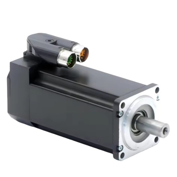







Description
-
BrandB&R
-
Model8MSA4L.R0-31
-
Product NameThree-phase Permanent Magnet Synchronous Servo Motor
-
Place of OriginAustria
-
Customs HS Code85015200
-
Power Supply330 V AC
-
Dimensions110mm × 110mm × 165mm
-
Weight7.7 kg (without brake)
-
Operating Temperature-20°C ~ +80°C
-
Storage Temperature-40°C ~ +80°C
-
Warranty12 month
-
Product Statusnew
B&R 8MSA4L.R0-31 Wiring Instructions
The 8MSA4L.R0-31 belongs to B&R 8MS series permanent magnet synchronous servo motor with integrated holding brake. It is equipped with two independent connectors: power connector and encoder connector.
1. Power Connector (Motor Power & Brake)
Power pins:
U; Motor phase U
V; Motor phase V
W; Motor phase W
PE; Protective earth, connect to the PE terminal of the drive
Brake pins (integrated holding brake):
BRK+; Brake positive supply
BRK-; Brake negative supply
Brake rated voltage: 24VDC. The brake is activated when power is cut off and released upon 24VDC power supply.
Do not route brake wires to motor phase terminals.
2. Encoder Connector (EnDat 2.2)
This motor adopts EnDat 2.2 digital encoder interface. The pin assignment complies with B&R standard 615 series signal connector:
Clock +; Clock -
Data +; Data -
Encoder power supply +5V; Encoder GND
Shield; Cable shield, connect to motor housing and drive cabinet earth
3. Wiring Rules
Adopt dedicated B&R servo power cable and EnDat encoder cable; drag-chain compatible cables can be selected for relevant applications.
Cable shield shall be 360° terminated at both motor side and drive side to meet EMC requirements.
PE connection must be secured. Signal GND cannot replace protective earth.
Separate power cable and encoder cable during cabling, avoid parallel laying to minimize interference.
Full wiring inspection is required before power-on. Incorrect phase sequence will result in abnormal rotation.
Brake circuit: 24VDC control, which shall be managed by safety relay or brake output of the drive.

How to determine phase sequence for B&R 8MSA4L.R0-31
1. Factory Standard Reference
U, V and W pins of the power connector are defined on the motor nameplate and B&R cable specifications. When the drive’s U, V, W terminals are connected to the motor’s U, V, W in a one-to-one manner, the motor rotates clockwise (viewed from the shaft end), which is the factory default positive rotation direction.
2. Pre-Power-On Inspection
Use a multimeter in resistance mode to check the three-phase windings: U-V, V-W and W-U shall display low and approximately equal resistance values; the resistance between any phase and PE shall be infinite.
Verify the EnDat 2.2 encoder cable is fully wired and the shield is properly grounded. Improper encoder wiring may lead to failed phase detection or motor oscillation.
Ensure the 24VDC brake wiring (BRK+/BRK-) is separated from the motor power phases.
3. Commissioning via Automation Studio (Recommended)
This is B&R’s official commissioning procedure for ACOPOSmulti drives.
Complete all wiring for motor U-V-W and encoder cable; decouple the motor from mechanical load if feasible.
Launch Automation Studio and import the dedicated motor XML file for 8MSA4L.R0-31.
Run the motor identification / phase detection function in drive parameters. The drive will send test pulses to automatically identify phase alignment and encoder offset.
Once identification finishes, perform a low-speed jog test.
If rotation direction meets expectation: phase sequence is correct.
If rotation direction is reversed: swap any two of the U, V, W power cables OR invert the rotation direction via software parameter (software modification is preferred).
Do not swap encoder wires to change rotation direction for EnDat absolute encoders.
4. Manual Jog Test (Only for Failed Auto Identification)
Decouple the mechanical load and set a very low speed (e.g. 50 rpm).
Activate the jog command.
Case 1: Motor runs smoothly without vibration or overcurrent alarm → phase sequence is correct.
Case 2: Severe vibration, failed rotation, overcurrent / tracking error alarm → phase mismatch or encoder offset fault. Cut off power immediately, inspect wiring and restart motor identification.
5. Critical Safety Instructions
Disconnect power before modifying any wiring and wait for DC bus full discharge.
Do not execute phase detection while the motor is coupled to heavy mechanical loads.
Reliable PE connection is mandatory. Poor PE grounding causes EMC interference and false phase detection results.
Save drive parameters after phase verification and carry out mechanical homing test.
6. Troubleshooting Tips
Motor vibrates and cannot rotate: generally caused by incorrect phase sequence or faulty encoder connection.
Motor rotates in reverse: swap two power phase cables or invert rotation direction in software.
Failed automatic identification: check encoder power supply, EnDat signals, cable shield and connector crimp quality.



.jpg)
.jpg)







