






Description
-
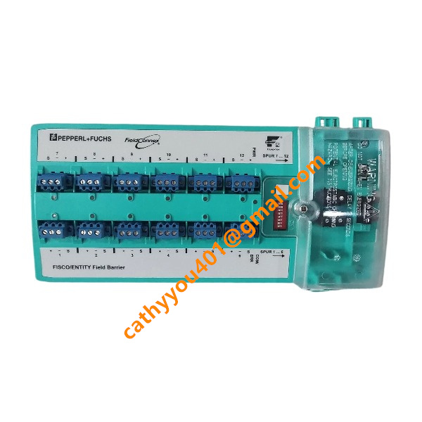
BrandPEPPERL+FUCHS
-
ModelR4D0-FB-iaa12.0
-
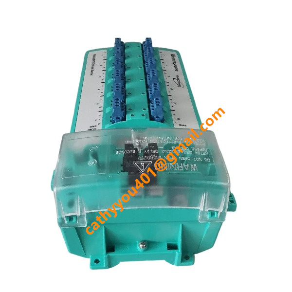
Product NameFieldbus Power Hub Segment Protector
-
Dimensions120 mm × 80 mm × 55 mm
-
Weight0.38 kg
-
Place of OriginGermany
-
HS Code85365000
-
Operating Temperature-40°C to +70°C
-
Storage Temperature-45°C to +85°C
-
Power Supply0.5 A
-
Warranty12 month
-
Statusnew and original
R4D0-FB-iaa12.0 PEPPERL+FUCHS Input and Output
Input (Trunk Fieldbus Input): This is the primary fieldbus trunk input interface. It receives 16 V DC to 32 V DC power together with FOUNDATION Fieldbus H1 / PROFIBUS PA communication signals from the host fieldbus segment. Reverse polarity protection is integrated into this port. The module can still operate at a minimum voltage of 15 V DC during temporary voltage dips. The trunk input supports up to 2 A pass-through current, and the maximum voltage drop from trunk input to trunk output is restricted to 100 mV. Built-in overvoltage surge protection triggers when the input voltage rises above approximately 39 V DC.
Trunk Output: The trunk output acts as a pass-through fieldbus port. It forwards the original fieldbus signal and power supply to downstream fieldbus barrier modules on the same main trunk. Up to 3 fieldbarrier units of this type can be cascaded on one individual fieldbus segment.
Fieldbus Spur Outputs: 12 independent Ex ia intrinsically safe spur output channels are provided. Each spur channel can connect one field instrument, and the maximum cable length for each spur is 120 meters. Every spur channel supplies rated voltage from 10 V DC to 14 V DC with a maximum individual output current of 43 mA. The total current consumption of all 12 spur channels is limited to 320 mA. Short-circuit current limiting is implemented on each spur; the short-circuit current is capped at 53 mA and falls to 1 mA under fault fallback conditions. All spur channels comply with FISCO and Entity intrinsically safe standards and adopt independent fault isolation design. A short-circuit fault on one spur branch will not affect communication of other fieldbus devices.
Diagnostic Signal Output: The module supports diagnostic status output. It transmits fault information including spur short circuit, spur open circuit, communication breakdown and internal module faults to the control system through the fieldbus.

R4D0-FB-iaa12.0 PEPPERL+FUCHS Output Signal Types
Spur Fieldbus Output (Ex ia Intrinsically Safe Fieldbus Signal): This is the main output signal type. It comes with 12 separate spur channels. Each channel transmits a composite signal combining DC power and digital fieldbus communication, supporting FOUNDATION Fieldbus H1 and PROFIBUS PA two-wire fieldbus protocols. Each spur supplies a rated voltage of 10–14 V DC and a peak output current of 43 mA to power one field instrument. Bidirectional digital process data, device parameters and diagnostic data are transmitted over the same cable pair. These outputs follow FISCO and Entity intrinsically safe specifications for use in hazardous locations. Each spur channel is equipped with independent short-circuit protection. The short-circuit current is limited to 53 mA and will decrease to 1 mA under fault fallback conditions. A short circuit on one spur branch will not interfere with communication on other fieldbus branches.
Trunk Pass-through Output: The trunk output acts as a bus pass-through interface. It preserves the original trunk fieldbus signal and power, and transmits FOUNDATION Fieldbus H1 / PROFIBUS PA signals as well as 16–32 V DC trunk power to the next cascaded fieldbus barrier modules on the same main segment. The maximum voltage drop between trunk input and trunk output is 100 mV. A maximum of 3 modules of this type can be cascaded on a single fieldbus trunk.
Diagnostic Fieldbus Output Signal: The module integrates diagnostic status data into the fieldbus communication signal. It sends digital fault information such as spur short circuit, spur open circuit, channel anomalies and internal module failures to the host control system through the fieldbus trunk. No independent hardwired discrete output contacts are needed; all diagnostic alarms are transmitted via digital fieldbus signals.
LED Indicator Output (Local Visual Status Signal): On-board LEDs provide local visual output signals. They display trunk power status, normal spur operation, spur short-circuit faults and module errors for on-site inspection. These LED indicators are only used for local status indication and do not provide external electrical signals.



.jpg)