





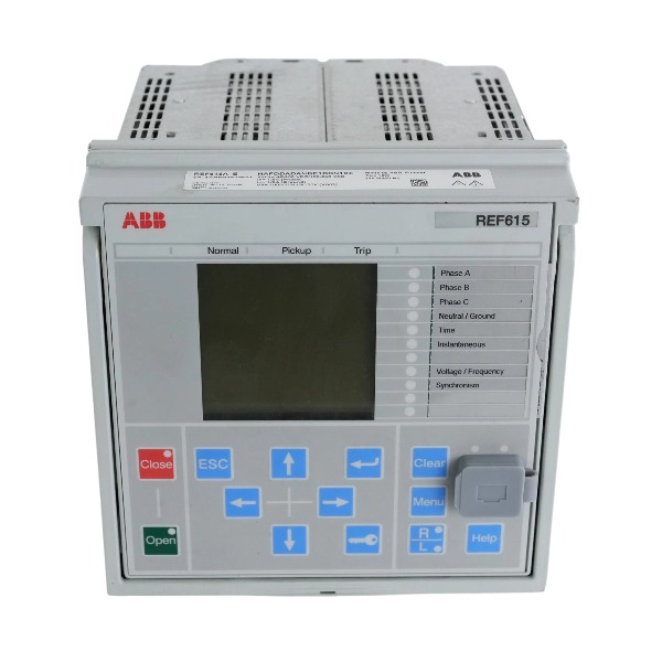
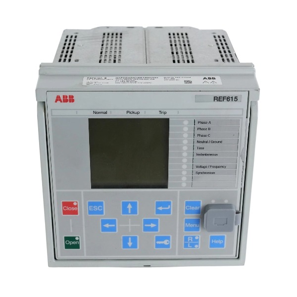
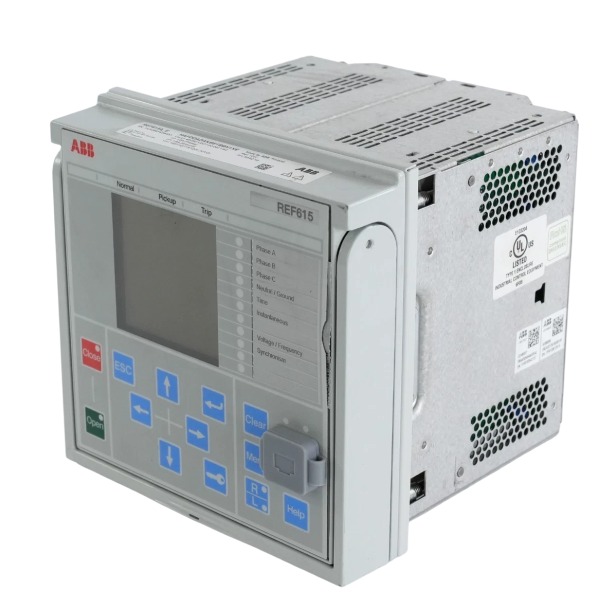







Description
-
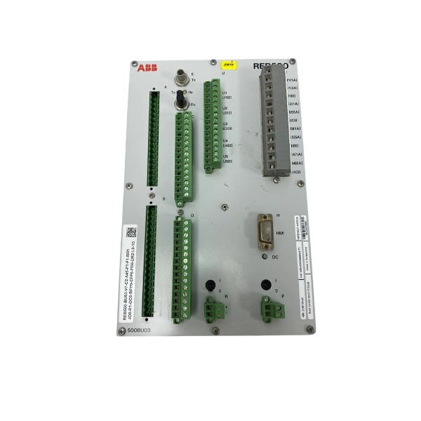
BrandABB
-
ModelREM615E
-
Product NameMotor Protection and Control Relay
-
Dimensions144 mm × 144 mm × 158 mm
-
Weight1.4 kg
-
Place of OriginFinland
-
HS Code85363000
-
Operating Temperature-25 ℃ to +55 ℃
-
Storage Temperature-40 ℃ to +85 ℃
-
Manufacturing part numberHBMBCAAJNEA1BBN1XG
-
Warranty12 month
-
Statusbrand new
Technical Document for ABB REM615E (HBMBCAAJNEA1BBN1XG)
1. General Description
The REM615E is part of ABB’s Relion® 615 series. It is a dedicated IED for motor protection and control, developed for asynchronous and synchronous motors deployed within medium‑voltage industrial distribution networks. This compact all‑in‑one device combines protection, control, metering, monitoring, fault recording and communication capabilities. It is widely applied in chemical, oil and gas, power generation, water treatment, mining and general manufacturing sectors. The part number HBMBCAAJNEA1BBN1XG denotes the IEC variant, equipped with abundant binary I/O, and supports optional RTD measurement and arc flash protection.
2. Analog Inputs
Current inputs: 3‑phase CT inputs with selectable secondary rated value of 1 A or 5 A; residual earth‑fault CT input, rated at 1 A / 5 A.
Voltage inputs: 3‑phase VT voltage inputs with a rated phase‑to‑phase voltage of 100 V; residual voltage input dedicated to earth fault detection.
Optional auxiliary analog inputs: Up to 6 RTD channels (Pt100 / Pt1000) and 2 channels of 4–20 mA analog input, used to monitor winding temperature, bearing temperature and field process signals.
3. Binary Inputs
14 optically isolated binary inputs.
Input type: Compatible with AC and DC wet contacts.
Typical applications: Circuit breaker position feedback, disconnector status indication, limit switch signals, interlock loops, local/remote selection and fault reset commands.
4. Binary Outputs
13 relay outputs in total, Form C contact type (NO/NC/COM).
High‑speed trip outputs: Designed for main motor tripping and fast arc protection operation.
Normal trip outputs: Used for protection‑initiated tripping and fault isolation.
Signal and alarm outputs: For warning indication, fault signaling, running status and ready status feedback.
Trip circuit supervision is supported for critical trip circuits.
5. Auxiliary Power Supply
Supply voltage range: 48–250 V DC or 100–240 V AC, 50 / 60 Hz.
Note: The 24–60 V DC power option is not available for this ordering code HBMBCAAJNEA1BBN1XG.
It features low standby power consumption and is well suited for substation DC UPS power supply systems.
6. Protection Functions
Thermal overload protection with thermal memory; locked rotor and jam protection; startup supervision; loss‑of‑load protection.
Phase overcurrent protection, earth fault protection and negative‑sequence current unbalance protection.
Overvoltage, undervoltage, overfrequency, underfrequency and phase reversal protection.
Optional high‑speed arc flash protection.
Additional functions include motor startup time monitoring, stall protection and current unbalance protection.
7. Control & Supervision Functions
Circuit breaker close and open control; local / remote operation switching.
Customizable motor startup interlock logic and embedded programmable logic, equivalent to internal PLC functionality.
Trip circuit supervision and comprehensive IED self‑supervision.
Metering functions: Three‑phase current, voltage, active and reactive power, power factor, energy, frequency and temperature.
Built‑in event log, disturbance recorder (oscillography), fault indicator and motor start counter.
8. Communication Protocols
IEC 61850 Edition 1 / Edition 2, GOOSE messaging, IEC 61850‑9‑2 LE process bus.
Redundancy support: PRP and HSR ring redundancy.
Modbus TCP, Modbus RTU over RS485.
DNP3 (TCP and serial), IEC 60870‑5‑103.
Time synchronization: IEEE 1588 PTPv2, IRIG‑B and SNTP.
9. Compatible Systems & Software
Commissioning software: ABB PCM600. It is used for parameter setup, logic programming, disturbance waveform analysis, firmware upgrade and function testing.
Compatible automation platforms: ABB Substation Automation System, third‑party SCADA, DCS and IEC 61850 digital substation systems.
It can interoperate with bay controllers, merging units, station HMI and historical data servers.
10. Environmental & Mechanical Specifications
Mounting type: Flush panel mounting for switchgear cabinets.
Operating temperature range: -25°C ~ +70°C.
Conformal coating is available as an option for corrosive and harsh environments.
Ingress protection rating: Front panel IP54, rear terminal area IP20.
Compliant standards: IEC 60255, IEC 61850, IEC 61010.
11. Typical Application Scenarios
Medium‑voltage motor protection for fans, pumps, compressors and conveyors.
Motor control cubicles and intelligent switchgear bay units for process industries.
Motor bays in digital substations adopting the IEC61850 process bus architecture.

1. Pre-installation Check
Verify that the part number HBMBCAAJNEA1BBN1XG meets your project requirements. Check the installation environment: the allowable operating temperature ranges from -25°C to +70°C. Avoid locations with severe vibration, corrosive vapors, direct sunlight and excessive humidity.
Prepare required tools including insulated screwdriver, torque wrench, anti-static wrist strap and multimeter. Isolate the corresponding bay, disconnect all power supplies and fully discharge capacitors prior to wiring work. Get ready the wiring diagram, CT/VT test block (RTXP18 recommended), and shielded twisted-pair cables for communication.
2. Panel Mounting
The REM615E supports flush mounting, semi-flush mounting, 19-inch rack mounting and Combiflex frame mounting.
The cutout size for standard flush mounting is 161.5±1 mm (height) × 165.5±1 mm (width). Insert the IED housing into the panel opening, attach the mounting brackets and fasten the screws with a torque of 0.7–1 Nm. Ensure the front sealing gasket is properly seated to preserve the IP54 front protection rating. Leave adequate ventilation space around the device for heat dissipation.
Once the housing is secured, insert the removable plug-in module into the housing and raise the locking lever to fix and seal the module.
3. Wiring Procedure
Protective earth
Run a short and thick cable from the protective earth terminal to the main cabinet earth busbar. Earthing connection shall be completed first before all other wiring.
CT current inputs
Route 1A/5A CT secondary conductors to the current terminals. Install test blocks on CT circuits. Always short the CT secondary before disconnection; an open CT secondary circuit is strictly prohibited.
VT voltage inputs
Connect VT secondary circuits (100 V phase-to-phase) to voltage terminals and residual voltage terminals. The VT secondary side must be solidly grounded.
Binary inputs
Wire breaker position feedback, limit switches, interlock signals, local/remote selection and reset dry contacts to the 14 optically isolated binary inputs. These inputs accept both AC and DC wet contact signals.
Binary relay outputs
Lay cables for Form C relay outputs for trip circuits, alarm signals and status indication. Activate trip circuit supervision for critical trip loops.
RTD and 4–20mA analog inputs (optional)
Connect Pt100/Pt1000 RTD sensors and 4–20mA transmitters to the dedicated auxiliary analog terminals. The 3-wire RTD wiring method is recommended to minimize measurement errors.
Auxiliary power supply
Supply 48–250 V DC or 100–240 V AC to the power terminals. Confirm the supplied voltage falls within the rated range of this specific variant.
Communication wiring
Ethernet port (IEC61850, Modbus TCP): Use shielded CAT5e cable with single-point shield grounding.
RS485 port (Modbus RTU, IEC 60870-5-103): Apply shielded twisted pair cable in bus topology; fit a terminating resistor at the far end of the bus.
Wire IRIG-B or PTP time synchronization lines according to system design.
4. Wiring Separation Rules
Physically separate CT/VT signal cables, power cables, binary signal wires and communication cables. Communication and analog signal cables must be shielded and routed away from high-current power cables to suppress electromagnetic interference.
5. Power-on and Commissioning
Perform a thorough inspection of all wiring, terminal tightening torque, earthing connections and CT shorting status before energization. Remove CT shorting jumpers once the inspection is passed.
Switch on the auxiliary power supply and confirm the IED boots up without hardware fault alarms. Establish connection with PCM600 via the front service port or Ethernet port, then download the protection setting file. Configure protection parameters, application logic, communication addresses and time synchronization.
Carry out binary input/output tests, CT/VT injection tests and protection function verification. Check event logs, disturbance recorder records and communication connectivity to SCADA or DCS. Save and lock the settings, complete the commissioning report and close the front seal.

FAQ for ABB REM615E HBMBCAAJNEA1BBN1XG Relion Motor Protection Relay
Q1: What is ABB REM615E HBMBCAAJNEA1BBN1XG?
A: The REM615E HBMBCAAJNEA1BBN1XG is a motor protection and control IED from ABB Relion 615 series. It integrates protection, measurement, monitoring and control functions for medium and low voltage asynchronous motors.
Q2: What protection functions does REM615E provide?
A: It supports overload protection, short-circuit protection, earth fault protection, phase unbalance, phase loss, locked rotor, overvoltage and undervoltage protection for electric motors.
Q3: What communication protocols does REM615E HBMBCAAJNEA1BBN1XG support?
A: This unit supports IEC 61850, Modbus, DNP3 and IEC 60870-5-103. It can connect to SCADA, DCS and substation automation systems for remote monitoring and control.
Q4: What are the typical application scenarios for ABB REM615E?
A: It is widely used in water treatment, oil & gas, chemical plants, mining, cement, power plants and manufacturing factories for pump, fan and compressor motor protection cabinets.
Q5: Can REM615E record fault waveforms and event logs?
A: Yes, it comes with built-in disturbance recorder and event log function. It stores fault oscillography and alarm records for post-fault analysis and troubleshooting.
Q6: Is the full part number HBMBCAAJNEA1BBN1XG important for replacement?
A: Very important. The suffix code defines hardware, CT rating, communication options, firmware and function package. We need the complete part number for accurate replacement.
Q7: Can REM615E be configured via PC software?
A: Yes. You can use ABB PCM600 software to set protection parameters, configure logic, update firmware and read fault data.

GDB021BE
Unitrol 1020
698B275U01
SM810K01
BC810K02
PP886
PBA800
RED615



.jpg)
.jpg)







