3F53CAF0702A44B793852036AEB4A3C3.jpg)
.jpg)







Description
-
BrandKUKA
-
Model00-117-336
-
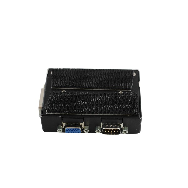
Product NameMFC3 Communication Interface Card
-
Place of OriginGermany
-
Customs HS Code85423190
-
Power Supply5mA
-
Dimensions100mm × 80mm × 40mm
-
Weight0.25kg
-
Operating Temperature-20°C to +55°C
-
Storage Temperature-40°C to +70°C
-
Warranty12 month
-
Product Statusnew and original
DSE-IBS-C33 (00-117-336) + MFC3 KRC2 Ed05 Full Signal List
Important note: The MFC3 motherboard has no user-accessible discrete digital or analog I/O terminals for field sensors. All signals listed below are internal system, servo and safety signals transmitted between MFC3, DSE, CI3, KPS, KCP and RDC drives. User peripheral I/O is implemented via the CI3 board or external DeviceNet I/O modules.
DSE-IBS-C33 (00-117-336, daughterboard mounted on MFC3)
Input signals: Encoder feedback from RDC over Interbus-S; Motor position and commutation feedback; Fault status of KSD servo modules; Drive temperature feedback; Drive current feedback; Interbus diagnostic reception; 5V power supply from MFC3 backplane; Real-time synchronization clock from MFC3.
Output signals: Axis position setpoint to servo drives; PWM and torque commands to KSD drives; Drive enable signal; Drive reset command; Interbus transmission to RDC; Servo fault status sent to MFC3.
Bus interfaces: Interbus-S (IBS) link to robot RDC; Parallel local bus to host MFC3 motherboard.
MFC3 Motherboard System I/O (KRC2 Ed05)
Input signals: Dual-channel local emergency stop (Channel A / B); Dual-channel external emergency stop (Channel A / B); Dual-channel enabling / deadman switch signal (A / B); Dual-channel safety guard door signal for operator protection (A / B); Single-channel external drive-off input; Single-channel external drive-on input; Operating mode selector signal (T1 / T2 / AUTO); Speed monitoring for Fan 1; Speed monitoring for Fan 2; Speed monitoring for Fan 3; Control cabinet housing monitoring signal; Power supply voltage monitoring; Temperature sensor input; KCP CAN bus receive; ESC safety node feedback from CI3; DSE card fault detection; DeviceNet CAN bus receive.
Output signals: ESC test pulse output A; ESC test pulse output B; Safety status signal to CI3 board; Drive contactor release request to KPS; KCP CAN bus transmit; DeviceNet CAN bus transmit; Real-time synchronization pulse to DSE-IBS-C33; Driving signals for diagnostic LEDs.

KUKA 00-117-336 DSE-IBS-C33 Common Faults & Solutions
Fault 1: Local Interbus-Master failure
Cause: Failed initialization of the Interbus master chip on DSE-IBS-C33; poor contact of card pins; abnormal 5V power supply of MFC3 backplane; mismatched card firmware; PCB hardware damage.
Solution: Completely power off the controller; take out the DSE card, clean gold-plated pins with contact cleaner and insert it tightly; measure 4.75~5.25V DC power of MFC3; confirm that the KSS version (KSS5.2/5.4/5.5) is compatible with firmware; test by replacing with a spare DSE card; replace the card if hardware is damaged.
Fault 2: DSE-IBS: Time-out while waiting for confirmation
Cause: Communication timeout between controller and servo drives; loose, damaged or aged green Interbus cable; faulty RDC base board; bus line interference; intermittent bad contact of DSE card.
Solution: Check and re-plug the Interbus ring cable; replace with a tested good Interbus cable; check the status of RDC board at robot base; eliminate high-frequency interference near cables; re-install DSE-IBS-C33 on MFC3; monitor bus communication via DSE-RDW diagnostic tool.
Fault 3: Error during DSE-IBS reset (boot failure)
Cause: DSE card reset error at startup; faulty MFC3 mainboard; hardware damage of DSE card; incorrect axis assignment of machine data $DSECHANNEL.
Solution: Cut off power fully for 30 seconds and restart; check MFC3 status and LED indicators; verify $DSECHANNEL axis configuration in machine data; restore robot archive backup; perform cross-test of DSE card on another KRC2 Ed05 cabinet; replace faulty DSE or MFC3 board.
Fault 4: DSE x not found / DSE axis assignment Ax error
Cause: MFC3 fails to identify DSE-IBS-C33; card identification failure; incorrect axis mapping parameters; exceeding the maximum limit of 2 DSE cards on one MFC3.
Solution: Ensure no more than 2 DSE cards are installed on one MFC3; reinstall the DSE daughterboard; check bent connector pins; verify axis assignment of machine data; reload valid machine data; inspect MFC3 backplane connector.
Fault 5: No connection to RDC / DSE-RDC communication error
Cause: Broken Interbus link between DSE and RDC; defective RDC board; open circuit of cable; communication circuit failure of DSE card.
Solution: Inspect the green Interbus cable between control cabinet and robot base; check LEDs and connectors on RDC board; test cable continuity; replace RDC board if defective; swap DSE card to locate the fault.
Fault 6: Axis not ready / Drive bus disturbance / All axes servo bus alarm
Cause: Abnormal servo link of DSE-IBS-C33; Interbus ring fault; defective KSD drive power module; error of encoder feedback channel.
Solution: Check status and LEDs of each KSD drive; carry out segmented test on Interbus ring and connect drives one by one; inspect motor encoder signal path; confirm drive enable signal output from DSE; check overcurrent and overtemperature alarms of KSD; calibrate $CURR_CAL current calibration data.
Fault 7: DSE board LED keeps red or flashes irregularly
Cause: Abnormal power supply for DSE card; internal chip crash of the card; short circuit on backplane; peripheral drive short circuit pulling down power voltage.
Solution: Measure 5V DC input current (rated 0.4A); disconnect Interbus cable to rule out downstream short circuit; restart the controller; check PCB for burn marks or bulging capacitors; replace defective DSE-IBS-C33.