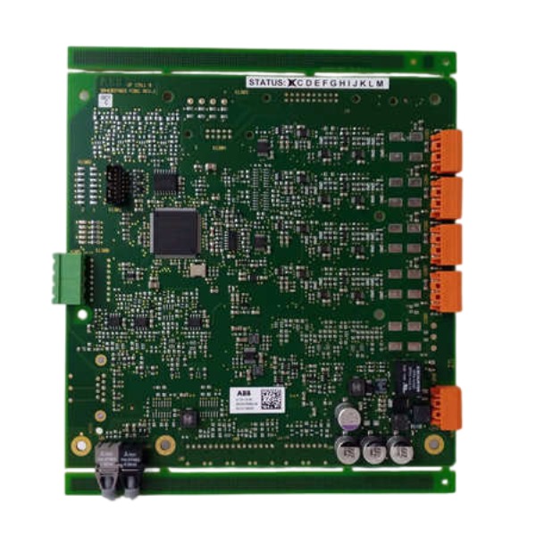
Description
-
BrandABB
-
ModelGDC801A
-
Product NameCrowbar Drive Control Board
-
Dimensions376 mm × 140 mm × 75 mm
-
Weight0.72 kg
-
Place of OriginSweden
-
HS Code85423190
-
Operating Temperature-25°C to +60°C
-
Storage Temperature-40°C to +85°C
-
Manufacturing part number3BHE024747R0101
-
Warranty12 month
-
Statusnew
ABB GDC801A 3BHE024747R0101 Wiring Method
Power connection: The circuit board receives 24 V DC power supply through the backplane. Check the polarity before installing the board onto the backplane to prevent reverse power supply that may cause permanent damage to the board.
Fiber optic connection: Link the Sercos III fiber ports of GDC801A to the AC800PEC main controller. Deploy dedicated industrial optical cables to build a closed Sercos ring topology. Keep fiber end faces clean and ensure proper insertion to achieve complete galvanic isolation between power circuit and control circuit.
Thyristor trigger wiring: Connect gate pulse output terminals to the gate-cathode loop of thyristors in the Rigi Crowbar circuit. Use shielded twisted pair cables for trigger signals and keep cables as short as possible to reduce interference. Trigger pulse cables must be routed separately from high voltage power cables.
RS485 Modbus RTU wiring: Connect RS485 A and B differential signal terminals to the DCS monitoring system. Select shielded twisted pair cables and ground the cable shield at a single point. Fit termination resistors at both ends of the RS485 bus segment.
Status signal wiring: Terminate fault and diagnostic signal terminals to remote monitoring I/O channels. Low-voltage signal cables should be laid separately from high-power cables to mitigate electromagnetic interference.
Grounding connection: Apply functional grounding for the board housing and cable shields. Single-point grounding is mandatory to avoid multi-point ground loops.
Pre-wiring check: Confirm all cable connections match terminal definitions. Inspect for short circuits and poor contact, and verify that optical fibers are intact without breaks.
Final inspection: Reconfirm power polarity, fiber connection direction, trigger wiring and bus termination before system power-up.

ABB GDC801A 3BHE024747R0101 Working Principle
The GDC801A serves as a Rigi Crowbar thyristor trigger drive board designed for the ABB AC800PEC real-time power electronics control platform. It is widely used in medium voltage drives including ACS2000 and ACS5000, functioning as the final hardware safeguard against DC bus overvoltage.
The module receives 24 V DC power from the backplane. It exchanges real-time control commands and diagnostic data with the AC800PEC main controller over a Sercos III fiber ring, delivering high-speed communication and galvanic isolation between the low-voltage control section and high-power circuit. In parallel, the RS485 Modbus RTU interface transmits operational states, fault codes and diagnostic metrics to the upper-level DCS monitoring system.
Its core protection logic relies on hardware threshold comparison rather than software-based decision making. The board performs continuous sampling of DC bus voltage. When overvoltage arises from grid fluctuations, regenerative energy spikes or commutation failures and exceeds the predefined threshold, the hardware circuit generates trigger pulses to the crowbar thyristors within microseconds. The thyristors activate instantly to create a low-impedance bypass loop, diverting surplus DC bus energy into the crowbar resistor bank, clamping the bus voltage and protecting IGCT power modules from destructive breakdown.
Once the protection sequence is executed, the board keeps tracking the restoration of bus voltage. As the voltage falls back to the normal operating range, the thyristor extinguishes naturally at the zero-crossing of current. The module then sends the crowbar activation record and fault status back to the main controller via the fiber channel.
This board incorporates on-board self-diagnostic capability. During normal operation, it persistently verifies the integrity of trigger channels, fiber communication quality and internal circuit conditions. Any detected anomaly will activate status alarms and lock trigger outputs to prevent unintended firing. A 2500 V AC isolation structure isolates high-voltage power circuits from low-voltage control circuits, reducing electromagnetic interference and enhancing overall system safety.

GDB021BE
Unitrol 1020
698B275U01
SM810K01
BC810K02
PP886
PBA800
RED615


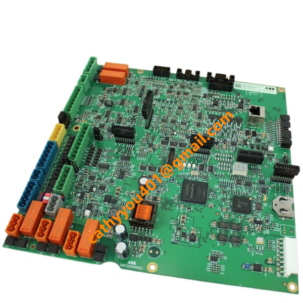

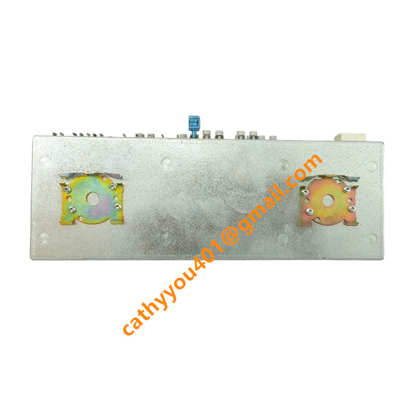
.jpg)