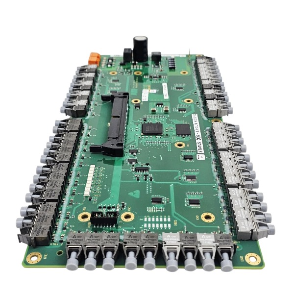
.jpg)
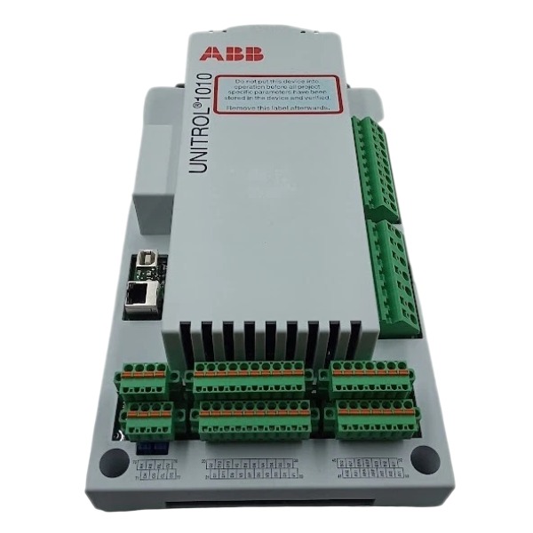







Description
-
BrandABB
-
ModelUNITROL1010
-
Product NameAutomatic Voltage Regulator (AVR) / Excitation Controller for Synchronous Generators
-
Place of OriginSwitzerland
-
Customs HS Code85371011
-
Part number3BHE035301R1002
-
Dimensions260 mm × 175 mm × 115 mm
-
Weight3.2 kg
-
Operating Temperature-40°C to +70°C
-
Storage Temperature-69°C to +70°C
-
Warranty12 month
-
Product Statusnew brand
ABB UNITROL1010 3BHE035301R1002 Input & Output Voltage / Current
Auxiliary Supply Input
100-240 V AC ±10 %, 50/60 Hz; 24 V DC as alternative option
Controller typical power consumption: approx. 250 mA
Excitation Main Power Input
3-phase AC: 0-300 V AC; maximum peak value 420 Vp
DC supply range: 0-420 V DC
PT Voltage Measuring Input (Generator Terminal Voltage)
3-phase AC measurement input, adapted for generator PT secondary, typical rating 100 V / 110 V AC
CT Current Measuring Input (Generator Stator Current)
AC current input sourced from CT secondary, standard secondary rating 1 A or 5 A
Digital Inputs
Nominal operating voltage: 24 V DC
Logic low threshold: 5 V; logic high threshold: 13 V
Input impedance: < 2 kΩ
Digital Outputs
Nominal rating: 24 V DC
Maximum continuous current: 150 mA per channel
Relay contact outputs are provided
Configurable Analog Inputs
Supported signal types: -2.5-+2.5 V, -5-+5 V, 0-5 V, 0-10 V, 0-20 mA, 4-20 mA
Input impedance: < 240 kΩ
Configurable Analog Outputs
Supported signal types: -10-+10 V, 0-20 mA, 4-20 mA
Output impedance: 100 Ω
Field Excitation Power Output
Continuous DC field current: 10 A DC @ 55 °C
10-second short-time overload current: 20 A DC
Continuous DC output voltage range: 0-200 V DC

Commissioning Procedure for ABB UNITROL1010 (3BHE035301R1002)
Pre-Commissioning Safety and Visual Inspection
Isolate all high-voltage circuits and allow sufficient time for capacitor discharge; ensure lockout-tagout procedures are properly implemented.
Examine mechanical installation, cooling gaps, protective earthing connections and cabinet EMC shielding integrity.
Double-check wiring for PT, CT, excitation supply, auxiliary power, as well as digital inputs and outputs. Physically separate power and signal cables to minimize electromagnetic interference.
Measure insulation resistance for exciter stator and rotor windings.
Get the commissioning laptop ready with installed CMT1000 software, USB or Ethernet communication cable and matching device firmware files.
Static Commissioning Tests (Generator Standstill Condition)
Establish physical connection between PC and UNITROL1010 through USB or Ethernet and set up stable CMT1000 communication link.
Retrieve device information to validate part number 3BHE035301R1002, installed firmware revision, hardware health status and historical alarm records.
Transfer pre-defined parameter configuration to the AVR unit. Enter generator nameplate data, base voltage setpoint, preliminary PID values and all limiter threshold settings. Store complete parameter dataset into non-volatile flash memory.
Carry out digital I/O simulation test to validate excitation enable command, trip signals, circuit-breaker feedback status and alarm relay outputs.
Complete static calibration for analog measurement channels, confirm PT voltage and CT current reading accuracy.
Reset and clear all existing active alarms and stored event logs.
No-Load Commissioning (Generator Running at Rated Speed)
Start the prime mover and accelerate the generator up to nominal rotational speed.
Activate MANUAL excitation mode. Raise the manual reference setpoint gradually and increase generator terminal voltage step-by-step to 50 % of rated voltage.
Cross-reference voltage and current readings displayed in CMT1000 against local panel meters and protection devices, confirm correct measurement polarity and reading precision.
Further increase excitation reference until terminal voltage reaches 100 % rated value.
Launch the built-in AVR Tuning Assistant within CMT1000 to optimize voltage regulator PID gains.
Conduct voltage step-response test with 3 %-5 % voltage deviation under MANUAL mode. Document overshoot magnitude, settling time and any oscillatory behaviour.
Shift regulator to AUTO voltage control mode, repeat step-response test and fine-tune PID parameters for smooth and stable dynamic performance.
Validate functional operation of all protective limiters, including over-excitation limiter, under-excitation limiter and V/Hz limiter.
Grid-Parallel Commissioning
Finish synchronisation sequence and close generator circuit-breaker for grid connection.
Keep regulator under AUTO voltage control. Modify voltage setpoint and verify reactive-power response direction: reactive power output shall rise with higher voltage reference.
If applicable, enable VAR or power-factor regulation mode for functional check; observe limiter performance while reactive load fluctuates.
Implement load step change test, continuously track excitation current, generator terminal voltage and limiter triggering status.
Review real-time alarms, event log history and oscilloscope traces captured by CMT1000 during load transition periods.
Final Acceptance and Documentation Handover
Save finalized parameter configuration into AVR internal flash memory. Export parameter file, event logs and oscilloscope recordings for local PC backup.
Perform comprehensive alarm simulation test and verify all trip protection functions.
Preserve full commissioning records, test response curves and final optimized PID settings.
Dismantle temporary test instruments, restore original field wiring and release lockout-tagout permits.
Provide on-site operator training covering local unit operation, alarm diagnosis and basic fault troubleshooting using CMT1000 tool.

GDB021BE
Unitrol 1020
698B275U01
SM810K01
BC810K02
PP886
PBA800
RED615



.jpg)