.jpg)
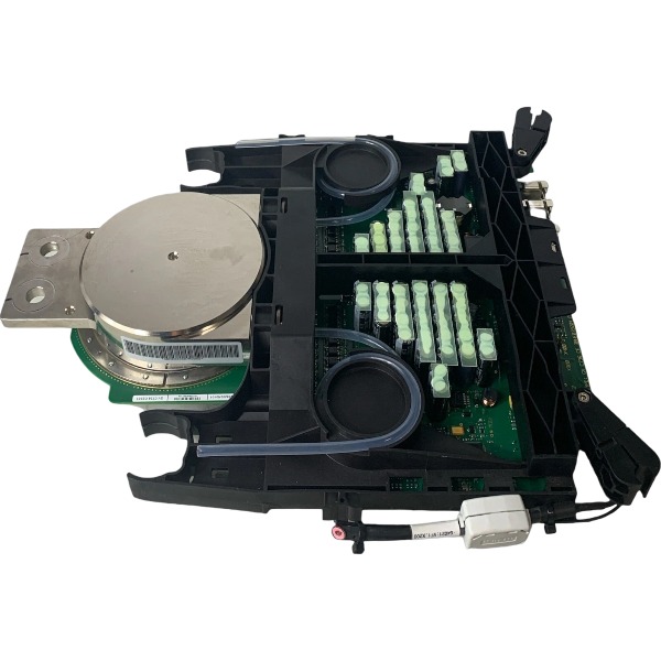







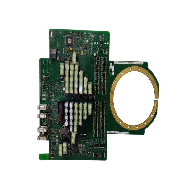
Description
-
BrandABB
-
Model5SHY4045L0004
-
Product NameIntegrated Gate-Commutated Thyristor (IGCT) Power Module
-
Place of OriginSwitzerland
-
Customs HS Code85415000
-
Part number3BHB021400R0002
-
Dimensions240 mm × 130 mm × 80 mm
-
Weight6.8 kg
-
Operating Temperature-40℃ to +125℃
-
Storage Temperature-40℃ to +130℃
-
Warranty12 month
-
Product Statusnew
Installation Steps for ABB 5SHY4045L0004 (3BHB021400R0002) IGCT Module
Implement lockout-tagout procedures to isolate the main high-voltage AC supply and the 24 VDC auxiliary control power. Fully discharge all DC-link capacitors and confirm zero potential on the DC bus using a calibrated high-voltage multimeter. Wear an ESD wrist strap properly bonded to a dependable protective earth point.
Unpack the IGCT module and visually inspect it for mechanical defects including cracks and surface contamination. Confirm that the part number corresponds to 5SHY4045L0004 / 3BHB021400R0002.
Disconnect fiber-optic gate links and auxiliary power wiring from the gate drive unit within the converter stack. Release the clamping load on the press-pack heatsink assembly.
Extract the existing IGCT from the stack guide. Clean the mating surfaces of both heatsinks and the disc faces of the new IGCT with approved solvent to remove leftover thermal compound and contaminants.
Apply a uniform thin coat of high-performance thermal interface material to the module contact surfaces. Excessive thermal paste shall be avoided.
Fit the replacement IGCT into the stack guide with correct polarity and orientation matching the power circuit layout. Ensure the module sits fully seated between the paired heatsinks.
Tighten the stack clamping fasteners in a balanced, sequential pattern to reach the clamping force (kN) specified in the ABB datasheet. Uneven compression may result in degraded thermal transfer or module rupture.
Reconnect the fiber-optic gate cables and 24 VDC auxiliary conductors to the gate drive unit. Route fiber cables clear of high-current busbars to minimize EMI interference.
Inspect mechanical clearances, insulation gaps and all earthing connections. Verify that no debris is left inside the converter stack.
Conduct insulation resistance testing in compliance with system specifications. For water-cooled configurations, verify coolant circuit pressure and flow conditions.
Cancel lockout-tagout only once all visual and electrical inspections are satisfactory. Execute low-voltage pre-commissioning tests prior to applying full high voltage.
Energize the auxiliary control supply first, validate gate drive status feedback and diagnostic signals, then carry out system commissioning in stages.
Warning: This installation shall only be performed by qualified personnel trained by ABB. Refer to the official ABB IGCT stack manual for defined torque values, clamping force and cooling parameters. Incorrect clamping or ESD damage can cause permanent, catastrophic module failure.

High Voltage Test Procedure for ABB 5SHY4045L0004 (3BHB021400R0002) IGCT Module
Important note: Prior to insulation and hipot testing, disconnect gate drive fiber cables and the 24 VDC auxiliary power supply for gate drives to prevent damage to sensitive gate drive electronics. This test must only be carried out by qualified ABB-trained technicians. Refer to the converter system manual for precise test voltage and holding duration.
1. Pre-test Safety & Preparation
Implement LOTO (Lock-out / Tag-out) for the main AC input and all auxiliary power sources.
Fully discharge DC-link and snubber capacitors, and verify zero voltage using a calibrated high-voltage multimeter.
Isolate the IGCT stack from control boards, gate drive assemblies, fiber-optic links and low-voltage cabling.
Confirm the module is clamped at the specified force, heatsink contact surfaces are clean, and the cooling circuit is sealed for water-cooled variants.
Install safety barriers, warning notices and proper earthing for the hipot tester. Deploy a calibrated insulation tester or hipot tester equipped with high-voltage rated probes.
Validate environmental conditions: the area must be dry and free of condensation, with humidity within ABB-specified limits.
2. Insulation Resistance Test (Megger Test)
Attach one test probe to the IGCT power terminal (anode or cathode), and the other probe to protective earth or the heatsink.
Set the test voltage in accordance with converter documentation; DC insulation testing is standard.
Ramp the voltage up slowly, maintain the required test period, and record the insulation resistance reading.
Acceptance criteria: the measured insulation resistance must exceed the minimum limit stated in the system manual, with no abrupt surge in leakage current.
Thoroughly discharge the unit under test once the test completes.
3. Dielectric Withstand (Hipot) Test
Select either AC power-frequency hipot or DC hipot as defined in the converter manual. Never subject the IGCT chip to voltages exceeding its datasheet rating.
Increase voltage at a controlled slow ramp rate; full test voltage must not be applied instantaneously.
Sustain the specified test duration, normally 60 seconds, and continuously track leakage current.
Terminate the test right away if breakdown, flashover, corona discharge or sharp leakage current growth is detected.
For a passed test, gradually reduce the voltage to zero and conduct a complete discharge.
4. Low-Voltage Gate Function Test (Prior to High-Voltage Energization)
Reconnect fiber gate cables and the 24 V auxiliary supply after hipot testing and full discharge.
Execute low-voltage gate pulse testing with the main DC bus de-energized. Check gate drive status indicators, fiber communication integrity and turn-on / turn-off pulses.
Verify the desaturation protection feature of the gate drive unit.
5. System DC Bus Ramp-up Test
Reassemble all busbar connections, seal the cooling circuit and confirm proper coolant flow and pressure.
Energize the auxiliary control system first and confirm no gate drive faults exist.
Ramp the DC bus voltage incrementally from a low value to the rated level while monitoring leakage current, temperature and gate drive diagnostics.
Watch out for unusual acoustic noise, partial discharge and abnormal temperature rise.
Complete the no-load functional test before moving on to loaded commissioning.
6. Post-test Activities
De-energize the DC bus supply and discharge all capacitors again.
Remove test probes and reinstate all original wiring and fiber cable routing.
Record all measurement data, test timestamp and pass/fail status for documentation.

GDB021BE
Unitrol 1020
698B275U01
SM810K01
BC810K02
PP886
PBA800
RED615


.jpg)

.jpg)
.jpg)