





C8132602D2D54A1E9D1DBFC0BA122C66.jpg)
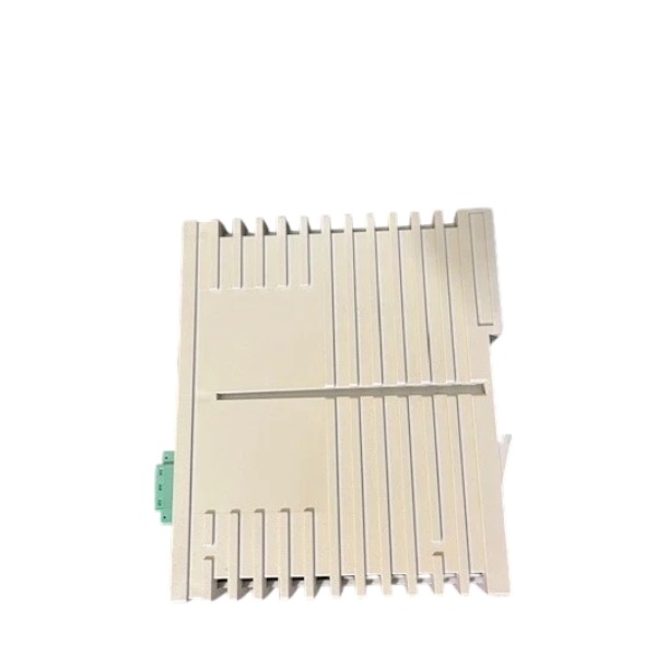







Description
-
BrandABB
-
ModelLD800HSE
-
Product NameFOUNDATION Fieldbus Linking Device
-
Place of OriginGermany
-
Customs HS Code85176290
-
Part number3BDH000320R02
-
Dimensions47 mm × 131 mm × 111 mm
-
Weight0.4 kg
-
Operating Temperature0℃ to +55℃
-
Storage Temperature-20℃ to +70℃
-
Warranty12 month
-
Product Statusnew
Features of ABB LD800HSE (3BDH000320R02)
Function: Serves as a gateway connecting FF H1 fieldbus segments to the high-speed HSE Ethernet subnet
Communication Ports: 4 × FF H1 channels with 31.25 kbit/s baud rate, galvanic isolation and removable 3-pole screw terminals; 1 × auto-sensing 10/100BASE-TX Ethernet RJ45 port; 1 × RS232 9-pin D-sub port at 115.2 kbit/s
Power Supply: 24 VDC with ±20% voltage tolerance; typical power consumption of 200 mA
Redundancy Support: Supports redundant configuration. A matched device pair communicates over a dedicated redundancy link to enable automatic failover and continuous H1 link supervision
Fieldbus Functions: Operates as LAS (Link Active Scheduler). It supports H1 device recognition, network management, function block access, cross-segment data republishing, as well as alarm and event forwarding
Mechanical Mounting: Designed for 35 mm standard DIN rail mounting
Enclosure Rating: IP20
Operating Temperature: 0 °C to +55 °C; Storage Temperature: -20 °C to +70 °C
Humidity Range: 0% to 95%, non-condensing
Standards Compliance: EMC meets EN 61000-6-2 and EN 61000-6-4; certified to UL 508 and CSA
Diagnostics: Integrated link status monitoring and fault indication for H1 and Ethernet communication channels
Typical Application: Enables integration of FOUNDATION Fieldbus field instruments with ABB 800xA and Freelance DCS systems

Installation and Configuration Procedure for ABB LD800HSE (3BDH000320R02)
Required Tools: Screwdriver, Ethernet cable, FF H1 fieldbus cable, 24 VDC power supply, laptop installed with Fieldbus Builder FF, IP network testing tools, lockout-tagout tags
1. Pre-installation Inspection and Safety
Carry out lockout-tagout procedures for cabinet power supply. Verify the part number LD800HSE, 3BDH000320R02 and inspect the module for mechanical damage, bent pins or contamination. Confirm ambient installation conditions: operating temperature ranging from 0 °C to +55 °C and relative humidity between 0% and 95% without condensation. Ensure adequate clearance around the module for heat dissipation. This linking device cannot supply power to FF H1 segments; external H1 power conditioners and bus terminators are mandatory for each H1 link.
2. Mechanical Mounting
Install the LD800HSE horizontally on a standard 35 mm DIN rail. Hook the upper latches onto the rail and press the module downwards until it locks firmly. Keep the recommended spacing between neighbouring modules to prevent overheating.
3. Wiring Connection
Connect 24 VDC power to the power terminals with a voltage tolerance of ±20%. Connect the 10/100BASE-TX Ethernet RJ45 port to the HSE subnet switch. Route FF H1 fieldbus cables to the 4-channel H1 terminal blocks, and fit proper bus termination to every H1 segment. For redundant deployment, lay the dedicated redundancy cable between the primary and secondary LD800HSE units prior to power-up. The RS232 D-sub port can be connected for local servicing when required. Double-check all wiring and eliminate potential short-circuit hazards before energization.
4. Basic IP and Web Initial Setup
Power up the module and observe the status LEDs. Connect the laptop to the HSE subnet or local service port. Access the built-in web server via the default IP address. Modify the static IP address, subnet mask and gateway to comply with the project HSE network scheme. Define the device name and other network parameters, save settings and reboot the LD800HSE. Confirm web accessibility after the reboot completes.
5. Configuration via Fieldbus Builder FF (800xA / Freelance)
Launch Fieldbus Builder FF on the ABB engineering workstation and import the device description file for LD800HSE. Add this linking device into the HSE subnet topology. Assign the LAS (Link Active Scheduler) role to each H1 link, and configure redundant LAS functions if a redundant pair is used. Scan H1 links online to discover connected FF field devices. Assign device tags, configure resource block parameters and download DD settings to field instruments. Develop function block applications, set timing schedules and cross-segment data publishing for H1 links. Configure alarm and event forwarding from H1 field devices to the HSE host system.
6. Redundancy Configuration (Optional)
Add the second LD800HSE as its redundant partner within Fieldbus Builder. Validate communication over the redundancy link. Configure failover logic and fault detection parameters. Test automatic switchover: the secondary unit shall take over the LAS function if the primary module fails or loses power.
7. Online Commissioning and Diagnostic Check
Download the complete configuration to the LD800HSE. Check module LED indicators for power, Ethernet, H1 link and redundancy states. Validate the H1 live device list, function block operation, process values, alarms and events on the DCS. Retrieve diagnostic data such as link noise, communication errors and module temperature through the web interface or Fieldbus Builder. Execute LAS handover tests for redundant configurations.
8. Post-commissioning and Documentation
Archive the full configuration file. Record the IP address, device tag, firmware revision, H1 network topology and all test results. Close cabinet doors and remove lockout-tagout locks only once all tests are passed.

GDB021BE
Unitrol 1020
698B275U01
SM810K01
BC810K02
PP886
PBA800
RED615



.jpg)
.jpg)
.jpg)







