_Cocoai.jpg)
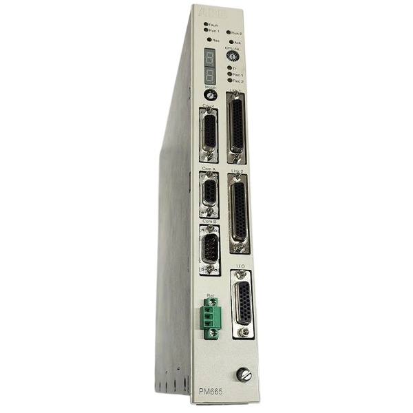







Description
-
BrandABB
-
ModelPM665
-
Product NameProcessor Module with Redundancy Voter
-
Place of OriginSweden
-
Customs HS Code85371091
-
Part number3BDS005799R1
-
Dimensions252 mm × 273 mm × 40 mm
-
Weight2.04 kg
-
Operating Temperature0 °C to 60 °C
-
Storage Temperature-40 °C to 85 °C
-
Warranty1year
-
Product Statusbrand new
Troubleshooting for ABB PM665 (3BDS005799R1) -AC800M / 800xA DCS Processor Module
The ABB PM665 is a high-availability processor module with hardware voter redundancy, designed for the ABB AC800M and 800xA DCS systems, widely deployed for critical process and turbine control applications.
1. Pre-Check & Safety Precautions
Power off and isolate control power before module removal. Avoid hot-swap operations unless the standby redundant processor is confirmed healthy.
Inspect cabinet operating conditions, including temperature, ventilation, dust accumulation and mechanical vibration.
Prepare troubleshooting tools: Control Builder M software, serial/Ethernet cables, spare PM665 module and official technical manuals.
2. PWR LED Off -No Power Supply
Measure 24 VDC input voltage at module terminals to confirm it meets the rated range.
Inspect cabinet fuses, loose terminals and broken power cables.
If input power is normal but the PWR LED remains off, the module has an internal power circuit failure and requires replacement.
3. RUN LED Off / Module Offline
Reseat the module to eliminate poor backplane contact issues.
Verify consistency between the module firmware version and Control Builder M project version.
Re-download the control project to fix missing or corrupted application files.
For redundant configurations, inspect the dedicated voter link cable between primary and standby PM665 modules.
4. Solid Red S-ERR LED -Severe Hardware Fault
Perform a full cold restart: power down the module for 3 minutes then restore power.
Retrieve fault codes and diagnostic logs via Control Builder M.
Typical faults include watchdog timeout, flash memory failure and internal hardware abnormality.
Replace the module if the S-ERR fault persists after rebooting.
5. Flashing S-ERR LED -Boot / Firmware Fault
Caused by incomplete firmware flashing or damaged firmware files.
Re-flash the matched official firmware through Control Builder M.
Do not cut power during the firmware upgrade process.
Continuous flashing failure indicates permanent module hardware damage.
6. I/O Bus Fault / Failed I/O Access
Check the status of CI801/CI810 fieldbus interface modules and rack backplane connections.
Inspect the I/O bus terminal termination resistor.
Eliminate bus short circuits and overload faults.
Verify that software configuration matches the physical I/O rack layout.
7. NET LED Alarm -Network Communication Fault
Inspect Ethernet cables, switch ports and physical link status.
Verify controller IP address, subnet mask, gateway and 800xA network configuration.
Ping the controller address and check switch port error counts and broadcast storm conditions.
For dual redundant networks, troubleshoot and verify both communication paths.
8. Redundancy Synchronization Failure
Inspect the dedicated redundancy voter cable for damage or poor contact.
Ensure primary and standby PM665 modules run identical firmware and application programs.
Check and adjust synchronization timeout parameters in Control Builder M.
Reset the standby processor and re-establish data synchronization if mismatch occurs.
9. Application Runtime Fault / Controller Shutdown
Troubleshoot program logic defects such as infinite loops and illegal memory access.
Check diagnostic logs for task overrun and watchdog trip alarms.
Optimize program cycle load or adjust task cycle parameters.
Inspect field I/O wiring for short circuits and overloads causing program exceptions.
10. System Clock & Data Retention Fault
Faults in system time reset and runtime data loss after power failure are mainly caused by low onboard backup battery voltage.
Replace the module backup battery and re-download the control application.
11. Standard Fault Recovery Procedure
1. Record all LED statuses and system diagnostic alarm information.
2. Back up the control project and system logs completely.
3. Perform a full cold reboot of the processor module.
4. Re-flash firmware or re-download the application program as required.
5. Conduct manual redundancy switchover testing after fault recovery.
6. Replace the PM665 module if faults cannot be resolved.

Working Principle of ABB PM665 (3BDS005799R1)
1. Hardware and Memory Architecture
The module adopts PowerPC CPU as the core, equipped with onboard RAM, Flash memory, real-time clock and backup battery.
Flash Memory: Permanently stores system firmware, user control applications and configuration parameters, retaining all data after power failure.
RAM: Serves as runtime memory for program operation, I/O image caching, control block calculation and system task scheduling.
Backup Battery: Maintains real-time clock operation and preserves volatile diagnostic data during power outages.
High-speed Special Input Circuit: Captures high-frequency pulse and speed signals, supporting turbine speed monitoring and overspeed protection functions.
Backplane Interface: Integrates power supply, I/O bus and redundant voter link interfaces for rack-level signal interaction.
2. Real-Time System and Task Scheduling
The PM665 runs ABB’s proprietary real-time operating system and supports IEC 61131-3 standard control applications downloaded via Control Builder M.
System tasks are scheduled based on priority and cycle time, with protection logic and closed-loop control tasks prioritized for execution. It operates in a cyclic scanning mode: collecting field input signals, executing control logic, calculating output values and refreshing I/O data.
An independent hardware watchdog monitors CPU operation in real time. It triggers system fault alarms and lights the S-ERR indicator once task overrun, program deadlock or hardware exceptions occur.
3. I/O Data Exchange Principle
The processor communicates with local S600 I/O and remote S800 I/O modules through the rack backplane and extended I/O bus.
It follows a three-stage cyclic control mechanism: input data acquisition, control logic computation, and output command execution. It completes signal collection, PID regulation, sequence control and safety interlock output.
With extended CI communication modules, it supports multiple field protocols including Advant Fieldbus 100, PROFIBUS DP and Modbus, realizing data interaction with remote I/O and third-party equipment.
4. Hardware Voter Redundancy Mechanism (Core Advantage)
Different from conventional network redundancy, the PM665 relies on onboard hardware voter circuits to implement dual-CPU hot standby within a single rack.
Two PM665 modules run identical firmware and application programs in parallel.
The dedicated high-speed voter link synchronizes all I/O data, program status and system parameters in real time.
The primary module executes control and output tasks, while the standby module keeps fully synchronized in hot-ready state.
The hardware voter continuously compares the operating status and calculation results of the two modules. It achieves bumpless automatic switchover upon primary module failure, ensuring uninterrupted process operation.
The faulty module supports online replacement, and the new standby module can automatically complete data synchronization to restore redundant configuration.
5. Communication Mechanism
Control Network: Adopts Ethernet + RNRP redundant routing protocol, builds dual redundant network paths to connect 800xA operator stations, engineering stations and other controllers, ensuring stable control transmission.
Engineering Interface: Supports serial and Ethernet access for firmware upgrading, project downloading and online diagnosis via Control Builder M.
Fieldbus Expansion: Matches CI series interface modules to expand fieldbus communication, connecting on-site I/O modules and industrial equipment.
All communication data is classified by priority, and high-priority control signals are guaranteed with optimized QoS to reduce transmission latency and jitter.
6. Full-Range Self-Diagnosis Function
The module performs uninterrupted background self-diagnosis during runtime, covering onboard power rails, RAM/Flash memory, CPU core, redundant voter link, I/O bus, network port and high-speed signal acquisition circuit.
All fault information is recorded in the internal diagnostic buffer, intuitively displayed through front-panel PWR, RUN and S-ERR LEDs, and uploaded to the 800xA system alarm platform. Specific fault codes can be queried via Control Builder M for accurate troubleshooting.
7. Power-On Boot Sequence
1. Power-on initialization: The onboard power circuit stabilizes power supply for CPU and peripheral hardware.
2. POST self-test: Automatically detects memory, voter circuit, backplane and peripheral devices.
3. Firmware loading: Reads and starts the real-time operating system from Flash memory.
4. Application initialization: Loads user control programs and initializes I/O images and communication stacks.
5. Redundancy synchronization: Completes data synchronization with the standby module (redundant configuration only).
6. Enables task scheduling and enters normal RUN operating state.

GDB021BE
Unitrol 1020
698B275U01
SM810K01
BC810K02
PP886
PBA800
RED615


.jpg)

.jpg)
.jpg)