





1D30565E36FA4931B428C359F190A567.jpg)
.jpg)
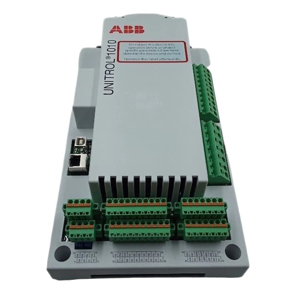







Description
-
BrandABB
-
ModelUNITROL 1010-0003
-
Product NameUNITROL 1010 BASIC Digital Automatic Voltage Regulator
-
Place of OriginSwitzerland
-
Customs HS Code85371011
-
Part number3BHE035301R0003
-
Dimensions240 mm × 160 mm × 80 mm
-
Weight2.2 kg
-
Operating Temperature-10℃ to +60℃
-
Storage Temperature-40℃ to +85℃
-
Warranty12 month
-
Product Statusoriginal
Commissioning UNITROL 1010-0003 (3BHE035301R0003) via CMT1000
Required Tools
Windows-based laptop with CMT1000 software, USB/Ethernet communication cable, digital multimeter, lockout-tagout toolkit, certified wiring diagrams, PT/CT signal test source
Pre-commissioning Safety & Preparation
Perform full lockout-tagout procedures on the generator prime mover, excitation power supply, generator main breaker and associated high-voltage circuits. Confirm the device model and part number as UNITROL 1010-0003 (3BHE035301R0003). Complete visual inspection and full wiring verification to eliminate wiring defects and hidden hazards. Install and initialize CMT1000 software on the laptop, and confirm USB drivers and Ethernet network settings are fully functional for normal communication.
Hardware Connection & Communication Setup
Connect the laptop to the UNITROL 1010 controller via the front-panel USB port or Ethernet port. Only apply auxiliary control power to the AVR, while keeping the main excitation circuit and generator equipment completely isolated. Launch CMT1000, select the corresponding USB or Ethernet communication channel and scan for online devices. Establish stable online connection with the target controller, then read and record the firmware version, and back up the factory default parameter file. Log into the password-protected CONTROL mode to unlock parameter modification privileges, as view-only mode restricts all configuration operations.
Base Machine Parameter Configuration
Access the configuration menu in CMT1000 to input complete generator nameplate parameters, including rated terminal voltage, rated frequency, rated field current, PT ratio, CT ratio and transformer vector group. Select applicable operating modes: automatic voltage regulation, manual field current regulation, VAR control or power factor control. Configure full protection limit parameters covering maximum/minimum field current, V/Hz limitation, overexcitation limitation, underexcitation limitation and stator current limitation. Define functional logic for digital inputs including excitation enable, de-excitation command, remote/local switching and breaker status feedback. Configure relay alarm outputs for AVR faults, overexcitation, PT signal failure and external tripping. Set up communication parameters including Modbus RTU/TCP slave address, baud rate and signal mapping; configure VDC node address to support reactive load sharing for parallel generator units. Download the completed configuration to the AVR’s non-volatile memory and save a backup file locally for project archiving.

Standstill Static I/O Test (Generator Stationary)
Keep the prime mover in shutdown and static state. View real-time data on the CMT1000 measurement interface to verify analog channel accuracy by injecting standard PT, CT and 4–20 mA test signals. Force digital input status via software to validate corresponding relay output and alarm actions. Perform full-range manual field current testing by ramping commands up and down steadily, confirming stable and linear output without saturation or abnormal fluctuation. Simulate typical faults such as PT signal loss and field overcurrent to verify rapid and reliable de-excitation protection response. Utilize the built-in oscilloscope function to capture operation waveforms for test records.
No-load Excitation Commissioning and PID Tuning
Run the generator to rated speed with no load. Activate excitation under manual mode firstly, slowly increase the field current setpoint via CMT1000, and verify the consistency of field current output and terminal voltage variation. Cross-compare measured values between CMT1000 and external precision meters. Switch to automatic voltage regulation mode and calibrate the terminal voltage to rated value. Adopt the built-in AVR tuning assistant to conduct voltage step response tests, and optimize PID parameters to eliminate overshoot, suppress system oscillation and shorten stabilization time. Verify the validity of the V/Hz limiting function by lowering the generator speed and checking normal limiter activation.
Grid-connected Test and Bumpless Mode Transfer
Synchronize the generator with the grid and close the main breaker. Enable VAR or power factor regulation functions according to operational requirements. Conduct mode switching tests between automatic and manual control via CMT1000, ensuring bumpless transfer without sudden field current surges. For multi-generator parallel systems, enable VDC reactive load sharing function and fine-tune parameters to achieve balanced reactive power distribution. Test remote setpoint adjustment through Modbus RTU/TCP communication, confirming stable data interaction and real-time value refresh between DCS/SCADA and the AVR controller.
Load Test, Limiter and Protection Verification
Implement graded active and reactive load tests on the generator. Monitor terminal voltage, field current, reactive power and all limiting functions in real time via CMT1000 trend windows. Apply heavy inductive and capacitive loads to verify overexcitation and underexcitation limiting performance. Simulate PT signal loss faults to confirm the AVR automatically switches to manual mode as configured. Export event logs and waveform records from the CMT1000 data logger for fault analysis and commissioning documentation.
Final Backup, Log Export and Handover
Save the finalized optimized parameter set to the AVR controller, and export all configuration files, event histories, oscilloscope waveforms and tuning reports for permanent archiving. Clear all resolved active alarms and reset fault records. Remove all temporary test cables and restore on-site wiring to original as-built status. Disconnect the laptop and complete software commissioning work. Provide on-site training for operators covering real-time data monitoring, alarm judgment and emergency manual de-excitation operation via the local MMI panel.

Operation Guide for ABB UNITROL 1010-0003 (3BHE035301R0003)
Perform complete lockout-tagout procedures for the generator prime mover, excitation power supply, generator main circuit breaker and high-voltage auxiliary circuits. Verify the device model is UNITROL 1010-0003 with part number 3BHE035301R0003. Conduct visual inspection to check for mechanical damage, burnt components, loose terminals and defective connectors. Inspect the connection quality of PT voltage input wiring, CT polarity wiring, excitation power terminals and field output cables. Standardize cable layout: isolate signal cables from high-power excitation cables, and implement single-point grounding for cable shielding. Test insulation resistance of field output terminals against the chassis to eliminate hidden short-circuit and grounding faults.
Wiring Verification
Verify all terminal connections strictly in accordance with approved schematics, including three-phase PT voltage measurement circuits, CT current sampling inputs, equipment auxiliary control power, IGBT excitation power supply and field winding output circuits. Calibrate 3 analog inputs, 2 analog outputs and all digital I/O signals covering excitation start, de-excitation command, breaker status feedback, external trip signal and alarm relay output. Confirm the RS485 bus termination resistor is correctly installed for Modbus and VDC communication. Inspect Ethernet connection integrity for CMT1000 debugging and Modbus TCP remote control. Ensure the de-excitation circuit adopts standard fail-safe design.
Power On and Communication Establishment
Only release the lockout-tagout for AVR auxiliary control power, while keeping the generator main circuit and excitation high-power circuit fully isolated. Supply rated auxiliary power to the UNITROL 1010 device and observe onboard LED status indicators. Connect the laptop to the device via USB or Ethernet, complete IP configuration, and establish stable online communication through CMT1000 software. Record the device firmware version, back up factory default parameters before any modification, and check for active hardware faults including PT signal loss, CT abnormality, field overcurrent and internal power supply failure.
Parameter Configuration (CMT1000 / Local MMI)
Log in to the configuration interface with authorized password. Input standard generator nameplate parameters: rated terminal voltage, rated frequency, rated field current, PT ratio, CT ratio and transformer vector group. Select applicable control modes: automatic voltage regulation, manual field current regulation, VAR regulation or power factor regulation. Configure full protection limiting functions, including field current upper/lower limit, V/Hz limiting, overexcitation limiting, underexcitation limiting and stator current limiting. Define digital input functions such as excitation enable, forced de-excitation, local/remote switching and breaker closed feedback. Configure digital alarm output signals for AVR fault, overexcitation, underexcitation and PT signal failure. Complete communication parameter setup including Modbus slave address, baud rate and signal mapping; configure VDC node address for reactive power sharing in multi-generator parallel systems. Save all configured parameters to non-volatile memory and export configuration files for project archiving.
Standstill Signal Test (Generator Static, No Rotation)
Keep the generator stationary and prime mover shut down, only power on the AVR device. Inject standard PT voltage analog signals to calibrate voltage measurement accuracy, and input CT current signals to verify current and power calculation precision. Force digital input signals via CMT1000 to check corresponding alarm and relay output actions. Conduct manual field output stroke test, ramp the field current command up and down to confirm stable and smooth output without oscillation or saturation. Simulate typical faults including PT signal loss, field overcurrent and external trip signals to verify rapid and reliable de-excitation response.
No-load Excitation Commissioning
Start the prime mover and run the generator to rated speed. Enable the excitation system under manual control mode first, slowly increase the field current setpoint, and check the consistency of field current response and generator terminal voltage change. Compare the device sampling data with PT secondary side measured values. Switch to automatic voltage regulation mode, adjust the terminal voltage to the rated value, optimize PID parameters of the voltage control loop through step response tests, and verify the normal operation of the V/Hz limiting function by reducing the generator speed.
Grid-connected Operation and Mode Switching
Complete generator synchronization and close the grid-connected breaker. Verify the operating performance of VAR or power factor control functions (if enabled). Test bumpless switching between automatic and manual control modes to ensure no sudden fluctuation of field current during mode transition. For multi-unit parallel operation systems, activate VDC reactive power load sharing function and fine-tune parameters to achieve balanced reactive power distribution. Test remote setpoint adjustment via Modbus TCP/RTU to confirm reliable remote control from DCS and SCADA systems.
Load Test and Protection Verification
Carry out graded active and reactive load tests. Real-time monitor terminal voltage, field current, reactive power and the operating status of all limiting functions. Verify overexcitation and underexcitation limiting protection under heavy inductive and capacitive load conditions. Simulate PT signal loss fault to confirm the AVR triggers fault protection and automatically switch to manual mode (if configured). Record the complete alarm sequence and event logs; the UNITROL 1010 can store up to 500 high-precision timestamped operation and fault events.
Normal Local & Remote Operation
Local MMI operation: view real-time operating parameters, switch control modes, adjust operating setpoints, and query active alarms and historical event records. Remote Modbus operation: realize excitation start/stop control, voltage/VAR setpoint modification, and remote upload of equipment status and alarm information. Normal shutdown procedure: reduce generator reactive load, open the grid-connected breaker, and issue de-excitation command to eliminate field voltage. Emergency protection: external digital trip signal triggers immediate forced de-excitation to ensure equipment safety.
Fault Diagnosis, Final Backup and Handover
Use CMT1000 software to query fault codes and event logs for professional troubleshooting. Clear historical alarms after fault elimination. Back up the final optimized parameter set, operating trend data and test reports. Restore all jumpers and field wiring to as-built status, and remove all temporary test cables and tools. Complete project data archiving, and conduct operational training for on-site operators covering mode switching, alarm identification and emergency de-excitation operation.

GDB021BE
Unitrol 1020
698B275U01
SM810K01
BC810K02
PP886
PBA800
RED615


.jpg)

.jpg)
.jpg)







