8737F9ACADB844439FB5201E582F9CA8.jpg)
.jpg)







Description
-
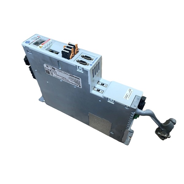
BrandAllen-Bradley
-
Model2094-BC02-M02-S
-
Product NameKinetix 6000 Integrated Axis Module
-
Place of OriginMexico
-
Customs HS Code850440
-
Power Supply324–528 VAC
-
Dimensions125 mm × 250 mm × 275 mm
-
Weight5.8 kg
-
Operating Temperature0℃ ~ +50℃
-
Storage Temperature-20℃ ~ +70℃
-
Warranty12 month
-
Product Statusoriginal
Wiring Method for Allen-Bradley 2094-BC02-M02-S
1. DC Bus Power Connection
This IAM adopts the shared power rail design of Kinetix 6000. Mount the module on the DIN rail and engage the backplane power connector to receive DC+ / DC- from the Line Interface Module (LIM, e.g. 2094-BL02).
The shared DC bus provides main power for inverters. Multiple axis modules share this DC bus via the power rail.
Tighten the power rail mounting screws to the required torque after installation.
Route high-power cables and low-voltage signal cables separately to mitigate EMI interference.
2. Motor Power Connector (MP)
Terminals: U, V, W, Protective Earth (PE)
Connect U, V and W terminals to three phases of the servo motor.
Link the motor protective earth wire to the PE terminal.
Fix the cable shield onto the drive shield clamp to achieve 360° shielding; pigtail shield connection is not allowed.
Select motor cables with matched current capacity and fasten terminals with specified torque.
3. Motor Brake Connector (BC)
Terminals: Brake+, Brake-
These terminals connect to the built-in holding brake of the servo motor.
The drive outputs DC control voltage to automatically release or engage the motor holding brake.
Leave this connector unconnected if the motor is not equipped with a holding brake.

4. STO Safe Torque Off Connector
It adopts a dual-channel STO safety circuit. Both STO channels must maintain closed state to activate drive power output.
Wire safety contactors, safety relays or digital outputs from safety PLC to STO pins.
STO wiring shall comply with SIL safety installation specifications. Cross connection between two channels is prohibited.
Once the STO circuit opens, the inverter power supply for the motor will be cut off, and motor torque will be removed.
5. Feedback & I/O Connector
Connect the encoder or resolver feedback cable of the motor to this port.
Differential encoder signals are supported. The encoder power supply is either 5V or 9V, determined by motor type.
Digital I/O pins are assigned for axis enable, fault output, home input, marker pulse and other axis logic signals.
Use shielded twisted-pair cables for feedback wiring, with the shield grounded at the drive end.
6. SERCOS Fiber Communication
SERCOS optical ports realize high-speed real-time motion communication between LIM and axis modules.
Apply daisy-chain topology: connect the fiber-out port of the preceding module to the fiber-in port of the next module.
Maintain the minimum bending radius of optical fibers; sharp bends and extrusion damage should be avoided.
7. Auxiliary 24V DC Control Power
24VDC supplies power for IAM control logic, feedback circuits, digital I/O and STO circuit.
Deploy an independent 24V DC power supply with fuse protection fitted on the positive line.
Correctly wire 24V+ and 24V-. Reverse polarity will cause permanent module damage.
8. Grounding
Install the module on a bare conductive backplate to form low-impedance protective earth connection.
All power cable shields, motor cable shields and module PE terminals shall be connected to protective earth.
Series grounding is forbidden; star grounding topology is recommended for the whole servo system.

Working Principle of Allen-Bradley 2094-BC02-M02-S
1. AC-to-DC Converter Stage
Three-phase 400/460V AC input enters the built-in converter. The rectifier converts AC into stabilized high-voltage DC bus (DC+ / DC-). This DC bus is distributed to all adjacent Axis Modules (AM) via the backplane power rail, forming a common DC-bus multi-axis architecture.
During motor deceleration, regenerative energy returns to the DC bus and raises bus voltage. The integrated shunt circuit activates automatically when DC bus exceeds threshold, dissipating excess regenerative power as heat to suppress overvoltage. Undervoltage, overvoltage and overcurrent protection monitor the converter continuously.
2. Servo Inverter Stage
The DC bus feeds the internal IGBT inverter. The control board outputs high-speed PWM signals to drive IGBTs, converting fixed DC voltage into variable-frequency, variable-voltage three-phase AC to drive the servo motor.
It implements three closed control loops: current loop (inner), speed loop (middle), position loop (outer). The controller compares the position command from the motion controller with actual motor position sampled from encoder feedback, calculates torque output in real time and adjusts PWM duty cycle, to achieve precise positioning, speed regulation and torque control.
3. SERCOS II Real-time Motion Communication
It communicates with the ControlLogix motion controller through SERCOS optical fiber daisy-chain. SERCOS transmits synchronized motion commands, axis status, fault information and encoder data with high determinism. All axes on the same power rail receive motion instructions synchronously to realize electronic cam, electronic gear and multi-axis coordinated motion.
4. Safe Torque Off (STO) Safety Circuit
This model has dual-channel STO function. When both STO channels are closed, the drive enables IGBT gate signals and motor torque is available. If either safety channel opens (triggered by emergency stop or safety relay), the hardware circuit immediately cuts off IGBT drive signals within <25 ms. The motor loses torque and coasts to stop (Stop Category 0). STO does not disconnect main power; it only disables torque output for machine safety protection.
5. Auxiliary Control & I/O Logic
24V DC control power supplies the control board, encoder feedback, digital I/O and STO circuit. Digital I/O handles axis enable, fault output, home trigger, marker pulse and brake control. The module automatically controls motor holding brake: release brake when axis is enabled, engage brake when axis faults or STO activates.
6. Protection & Monitoring Mechanism
Built-in real-time monitoring includes overcurrent, overload, IGBT overtemperature, DC bus over/under voltage, encoder fault, STO fault and communication fault. When a fault occurs, the module blocks PWM output, records fault codes and sends fault messages to PLC via SERCOS.
7. Common DC Bus Energy Sharing Principle
Under multi-axis configuration, the IAM supplies DC bus power for all AM modules on the same rail. When some motors regenerate power during deceleration, other axes on the rail can directly consume this regenerative energy, improving system energy efficiency. The shunt resistor only works when regenerative energy cannot be absorbed by other axes.

FAQ for Allen-Bradley 2094-BC02-M02-S
Q: What is Allen-Bradley 2094-BC02-M02-S?
A: 2094-BC02-M02-S is an Allen‑Bradley Kinetix 6000 integrated axis module, used as a servo power module for multi-axis motion control systems in industrial automation. It belongs to the Kinetix 6000 servo drive family.
Q: What series does 2094-BC02-M02-S belong to?
A: It is part of the Allen‑Bradley Kinetix 6000 servo drive series, designed for high-performance multi-axis motion applications.
Q: What industries use Allen-Bradley 2094-BC02-M02-S?
A: Widely applied in packaging machinery, material handling, textile equipment, printing machines, machine tools, robotics and automated production lines.
Q: What is the function of the 2094-BC02-M02-S integrated axis module?
A: It provides servo power and control for servo motors, realizes precise positioning, speed and torque control in multi-axis motion solutions.

6181P-17A3MWX1DC
1797-PS2N2
1756-PA50
1756-L81E
XM-161 1440-VDRS06-06RH
1440-DYN02-01RJ
SST-PFB3-CLX-RLL
MPL-B4530K-MJ72AA
6181P-17TSXP
6181P-12A2MW71DC
2711P-T12W22D9P
80026-520-01-R



.jpg)
.jpg)